


Finish on some not so good.
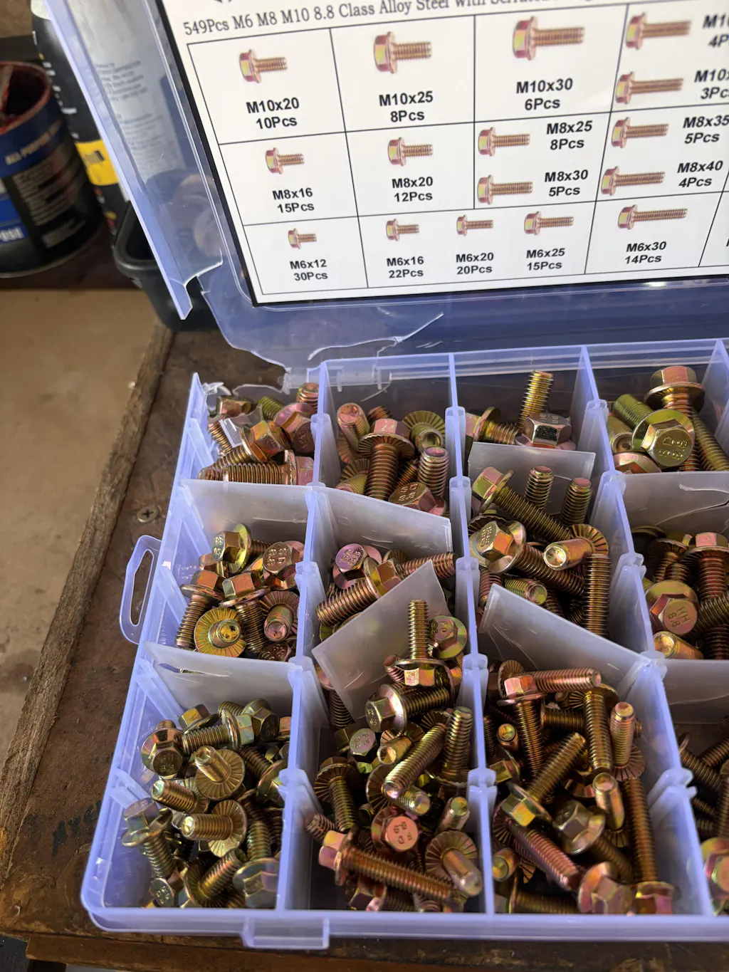
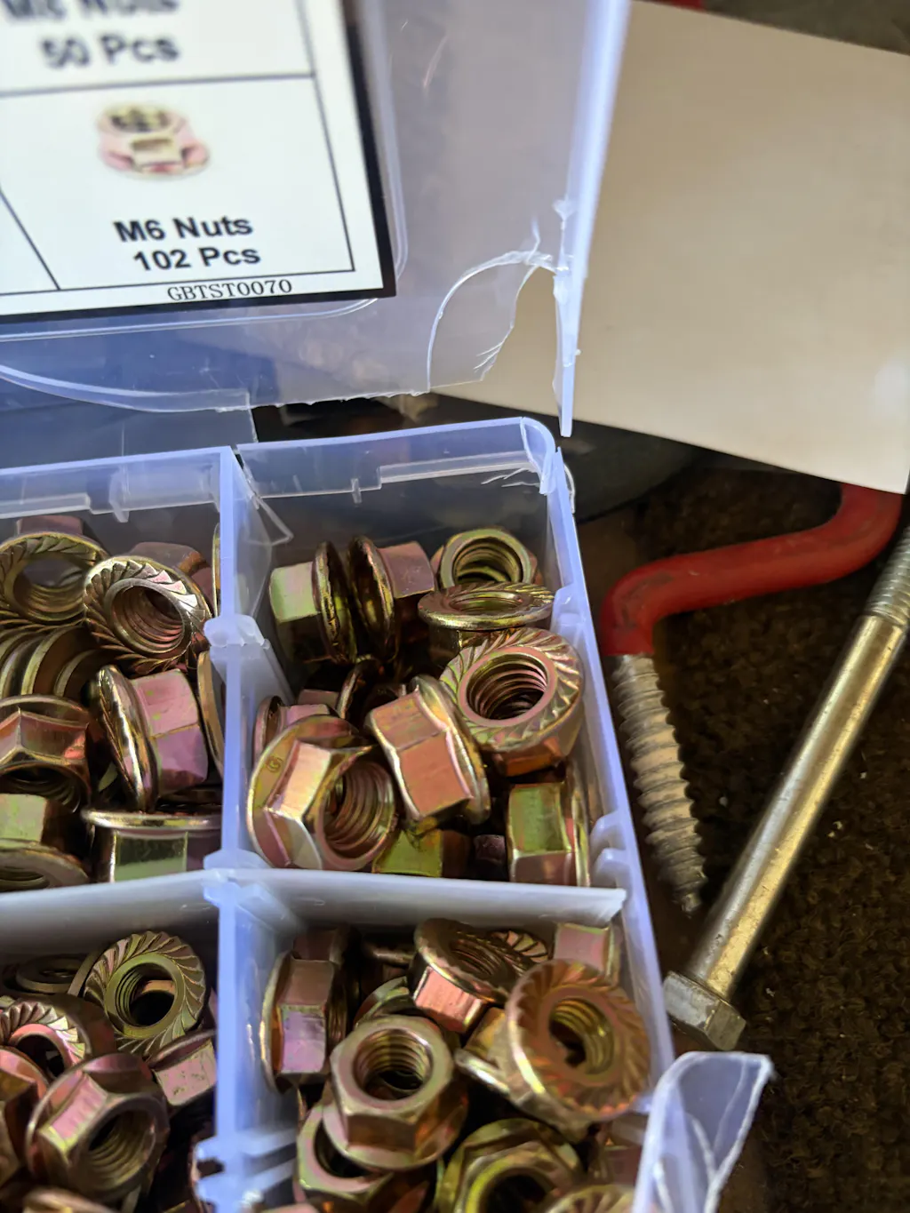
Plastic divider case arrived broken. Pretty much useless.
The chain is fine...but I ordered the wrong size. Nine links of the chain I ordered equals six of the size I wanted. My error...

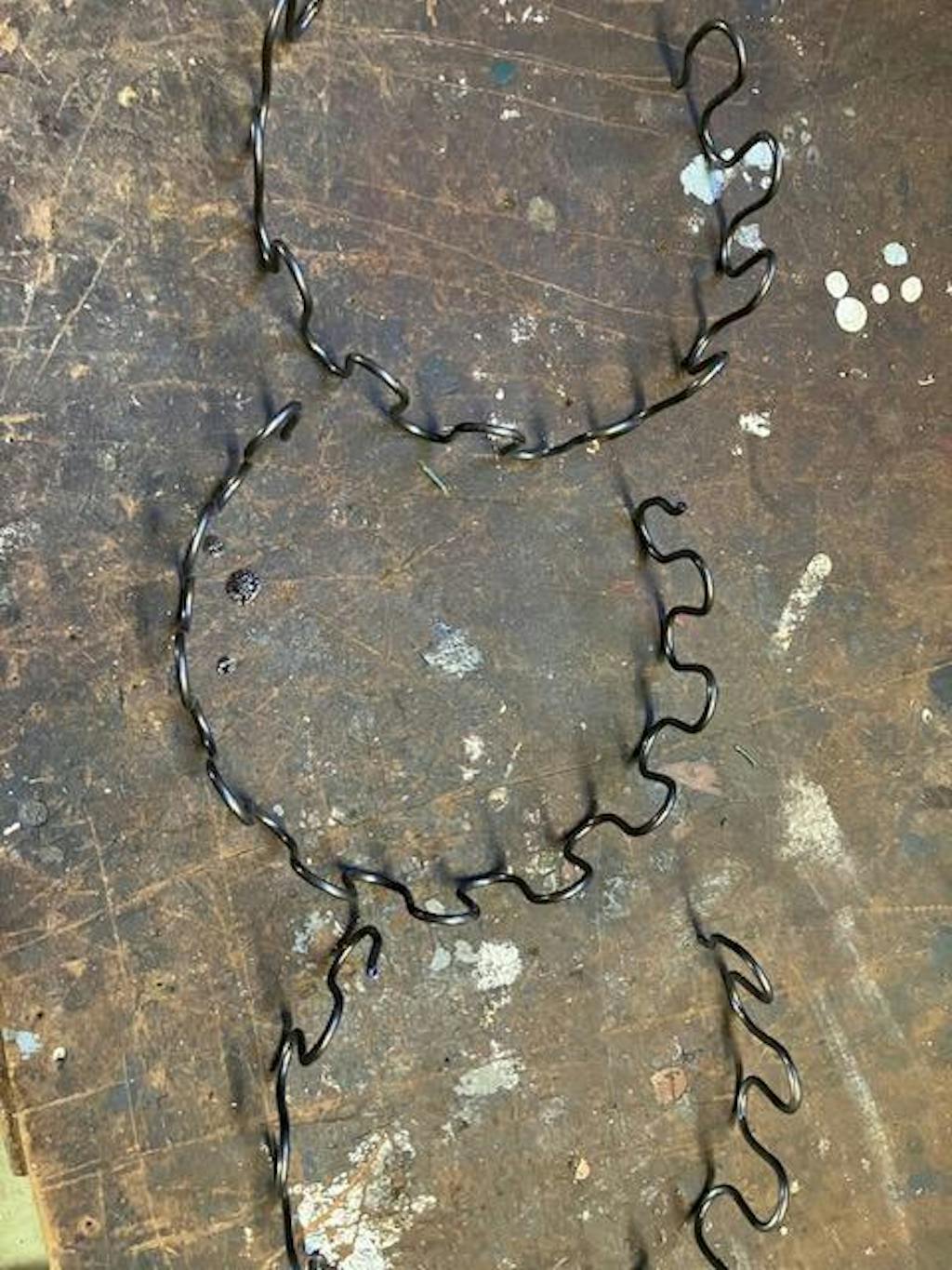
How can I straighten out the springs? I can't use them coil uo as is.

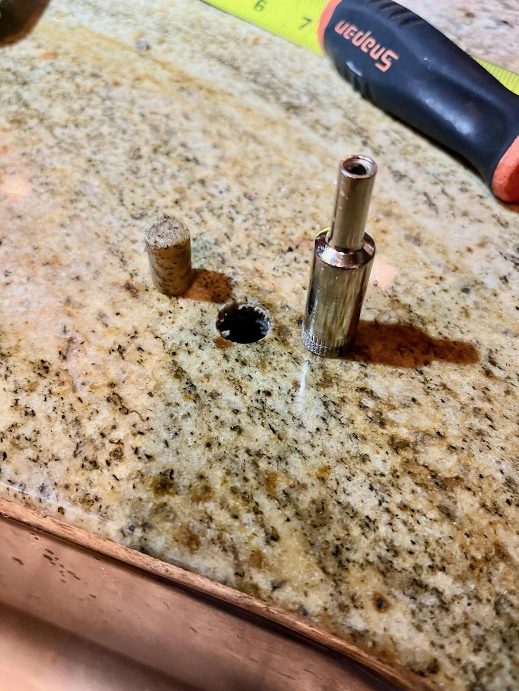
I was surprised these performed so well on my granite counter top considering the price! I thought I would go through all 5 bits but I successfully drilled through using only one bit. And it was sharp from start to finish!
I used plenty of water to lubricate, and took a few breaks to let the bit cool down.