
D40 * L66/L78 Flexible Plum Coupling Shaft Coupler CNC Stepper Motor 3D Printer

No reviews

Price:
Sale price$36.96 USD
Stock:
In stock (500 units), ready to be shipped

Payment & Security

Ach Direct Debit Amazon American Express Apple Pay Bancontact BLIK Diners Club Discover EPS Google Pay iDEAL Wero JCB Maestro Mastercard Multibanco MobilePay PayPal Przelewy24 Shop Pay Twint Union Pay USDC Visa

Your payment information is processed securely. We do not store credit card details nor have access to your credit card information.

Limited Offer — Spend More, Save More
Spend $55+
Save $5
Spend $100+
Save $10
Spend $200+
Save $25
HomeDIYer DIY Expert Support

DIY Expert Support

Get fitment advice & recommendations

Mon–Fri  8:30 AM – 8:00 PM
24-Hour Fast Ship
Arrives in 3–14 Days
Worldwide Shipping
30-Day Returns
1 tree planted with every purchase

Description

D40 Flexible Plum Coupling Shaft Coupler — Precision Motion for CNC & 3D Printing

When a rigid coupling transmits every vibration and misalignment straight into your spindle or lead screw, your print quality and machining accuracy suffer. The D40 Flexible Plum Coupling Shaft Coupler is engineered for hobbyists, makers, and workshop professionals who demand smooth, reliable power transmission between stepper motors and driven shafts — without the noise and wear that rigid couplings introduce.

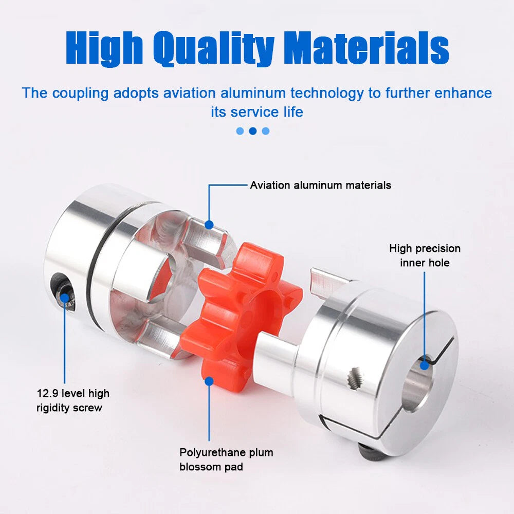
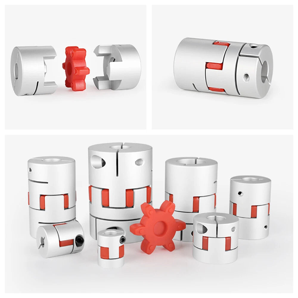
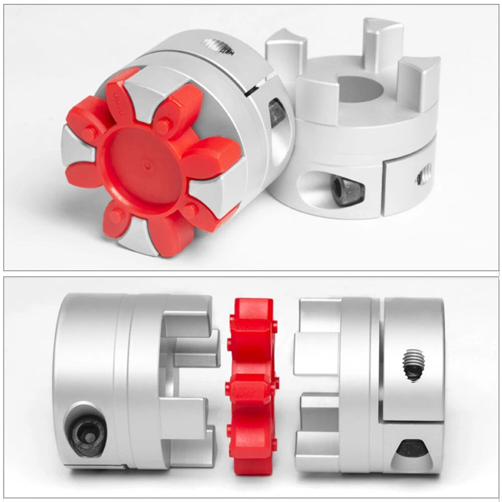
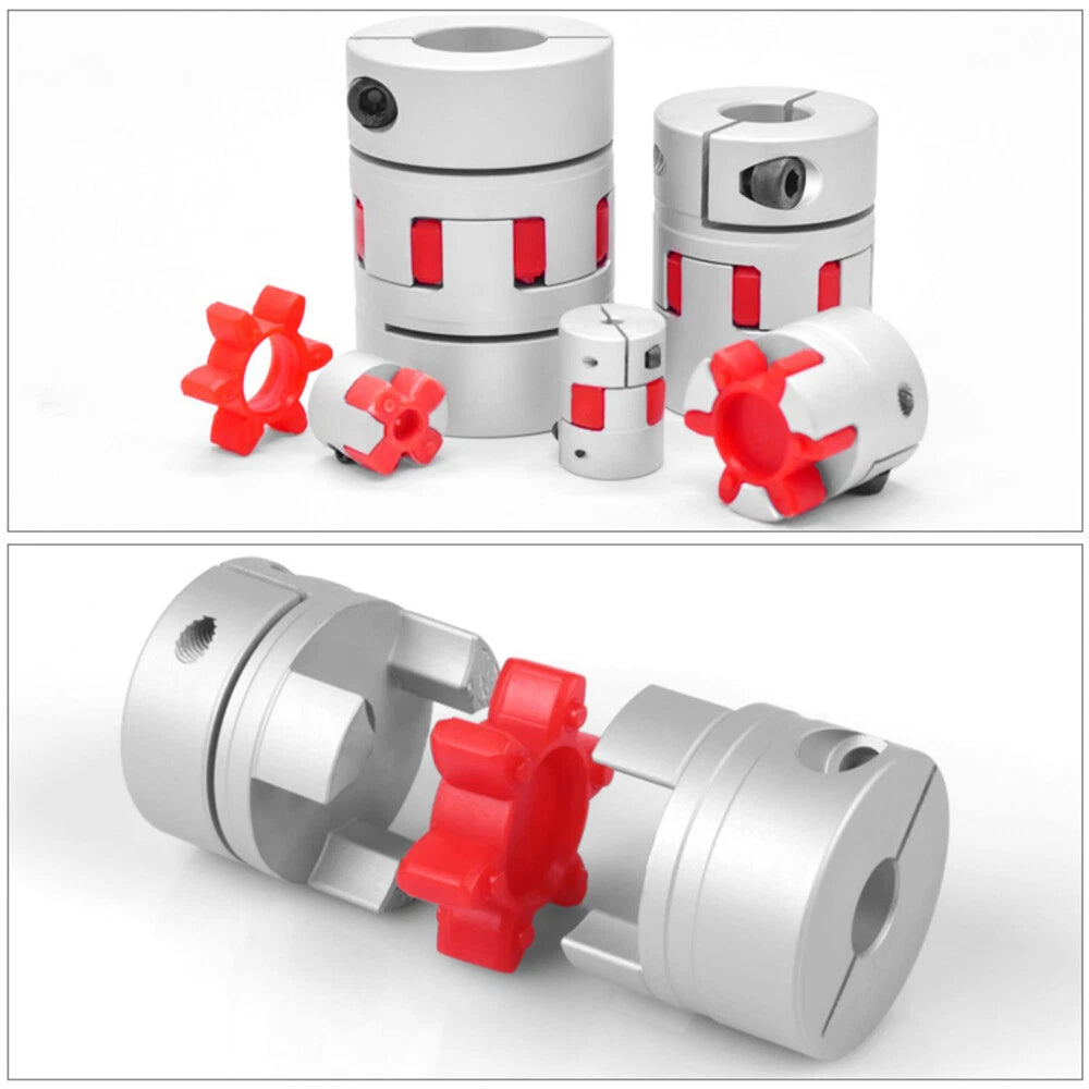
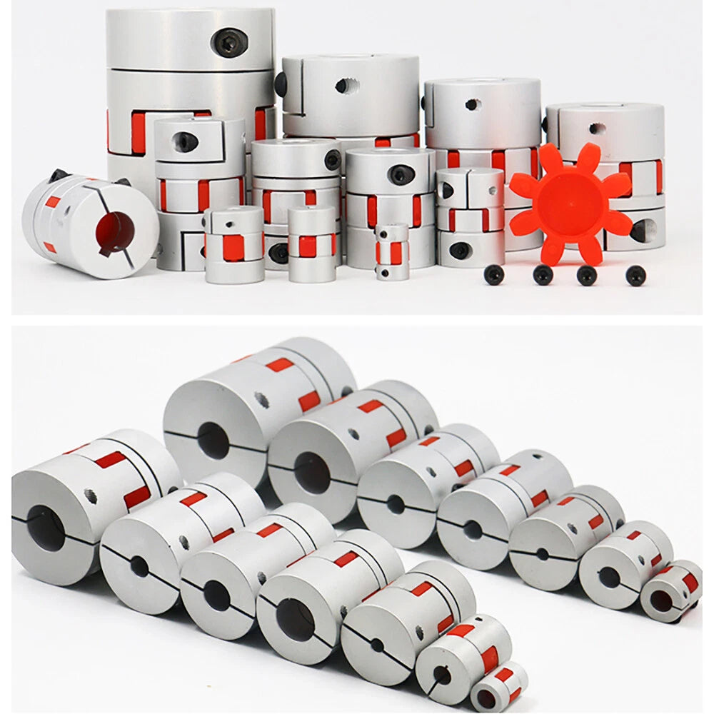
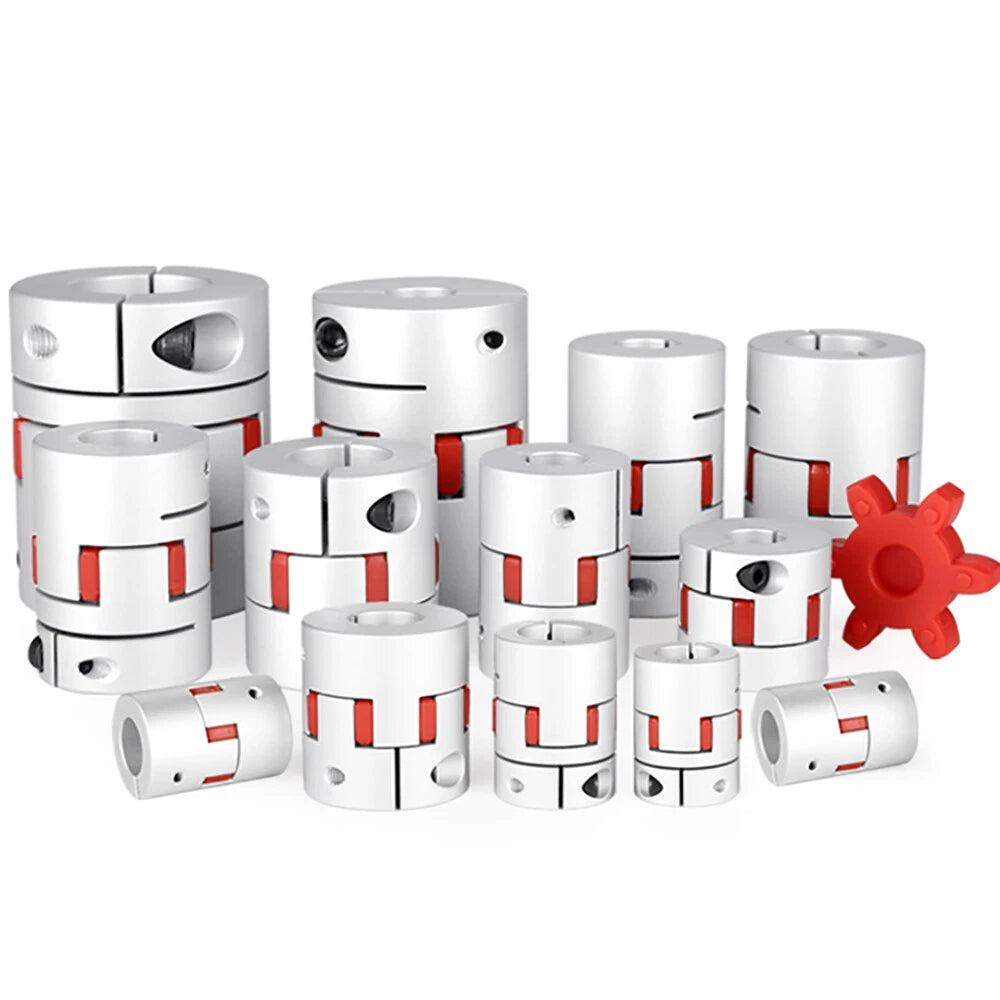
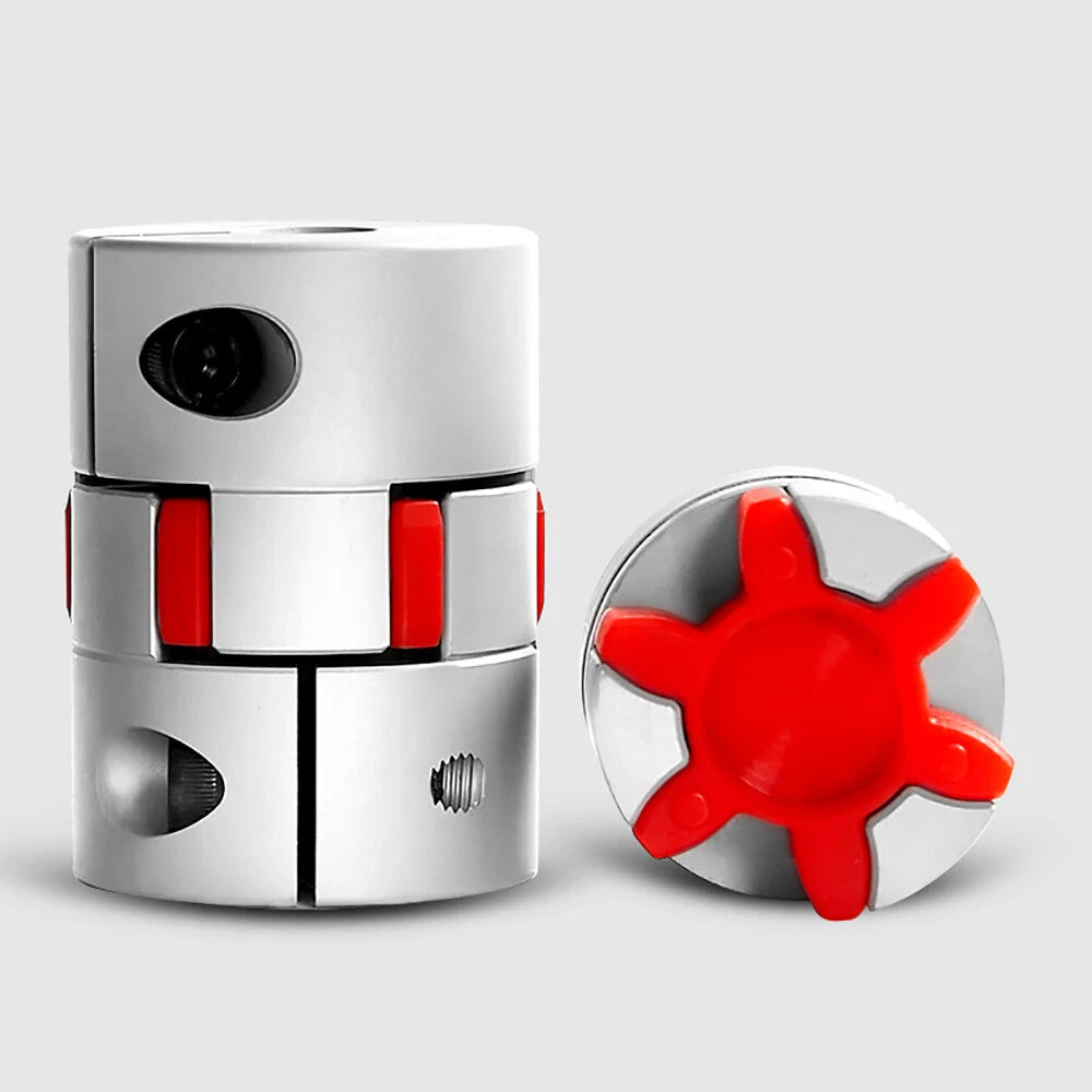
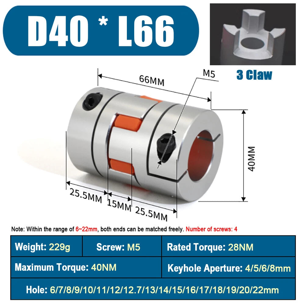
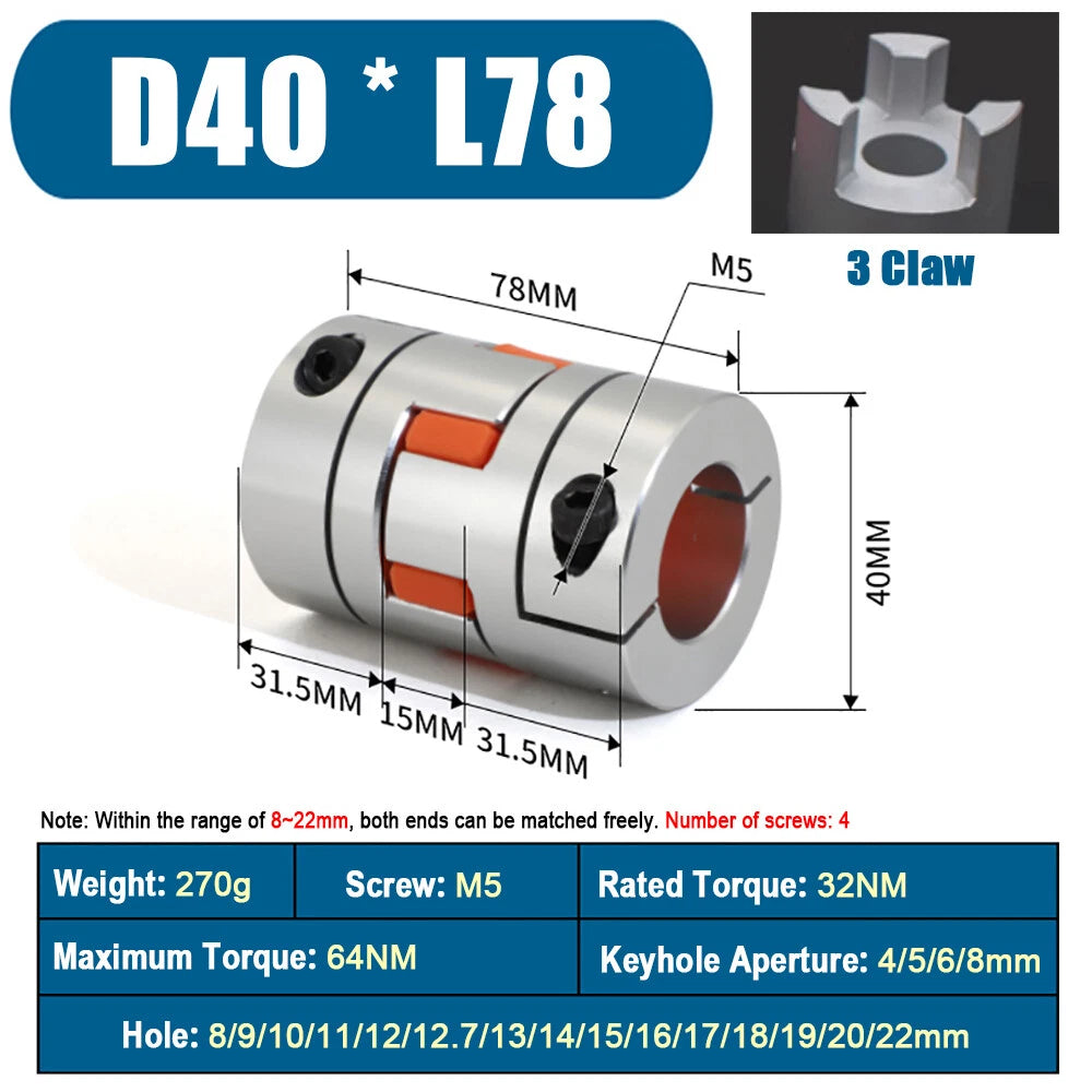
Each coupler consists of two precision-machined aluminum hubs and a polyurethane spider insert (plum element). The outer diameter is 40 mm (≈1.57 in), available in two body lengths: L66 mm (≈2.60 in) and L78 mm (≈3.07 in). Bore combinations range from 6 mm up to 22 mm on both the drive and driven sides, covering the most common stepper motor shaft and lead-screw diameters used in CNC routers, laser engravers, and FDM 3D printers.

Typical applications include connecting NEMA 17 / NEMA 23 stepper motor shafts to T8 or T12 lead screws in 3D printer Z-axis assemblies, coupling servo motors to ball screws in DIY CNC milling machines, and joining mismatched shaft diameters in small automation and robotics projects where angular or parallel misalignment compensation is needed.

Compatible with: NEMA 17 & NEMA 23 stepper motors · T8 / T12 / T16 lead screws · 6–22 mm motor and driven shafts · CNC routers, laser engravers, FDM 3D printers, and small automation systems

✅ Key Features of These D40 Flexible Plum Shaft Couplers

🔩
Dual-Hub Aluminum Construction

Both drive and driven hubs are machined from aluminum alloy, keeping rotating mass low while maintaining the structural rigidity needed for accurate torque transmission.

🌸
Polyurethane Spider Insert

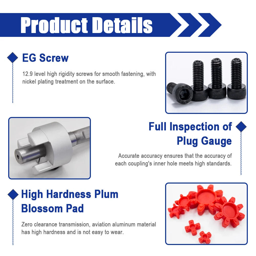
The six-lobe plum (jaw) element absorbs angular, parallel, and axial misalignment, dampening vibration before it reaches your linear rails or print bed — extending bearing and lead-screw life.

📐
Wide Bore Range: 6 mm – 22 mm

Available in dozens of bore combinations (d1 × d2) from 6 mm × 6 mm up to 22 mm × 22 mm, so you can match virtually any stepper shaft and lead-screw pairing without adapters.

📏
Two Body Lengths: L66 & L78

Choose the 66 mm length for compact motor mounts or the 78 mm version when you need extra clearance between motor face and driven component — both share the same 40 mm outer diameter.

⚙️
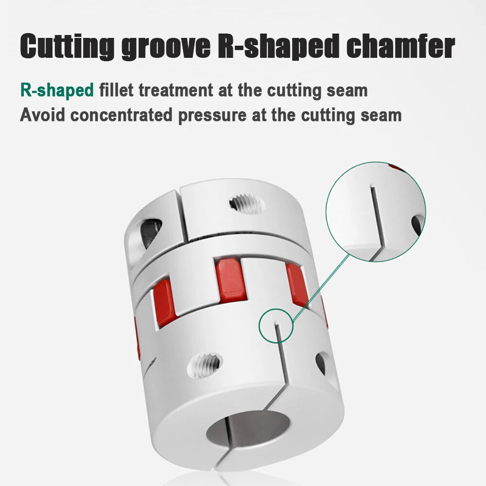
Set-Screw Clamping

Each hub is secured to its shaft with a radial set screw, providing a firm, slip-resistant grip without requiring keyways or press-fit tooling — easy to install and re-position.

🔄
Misalignment Compensation

Accommodates angular misalignment up to approximately 1°–3° and parallel offset up to approximately 0.2–0.5 mm, protecting your motor bearings and frame from stress caused by imperfect shaft alignment.

📐 Technical Specifications — Flexible Plum Jaw Coupling

Coupling Type Flexible Jaw (Plum / Spider)
Outer Diameter (D) 40 mm (≈1.57 in)
Body Length (L) 66 mm (≈2.60 in) or 78 mm (≈3.07 in) — see variant options
Bore d1 (Drive Side) 6 mm – 22 mm — see variant options
Bore d2 (Driven Side) 6 mm – 22 mm — see variant options
Hub Material Aluminum Alloy
Spider Insert Material Polyurethane (PU)
Clamping Method Set Screw
Angular Misalignment Typically 1°–3°
Parallel Misalignment Typically 0.2–0.5 mm
Finish Natural / Anodized Aluminum
Quantity per Order 1 piece

❓ Frequently Asked Questions

How do I choose the right bore combination (d1 × d2)?

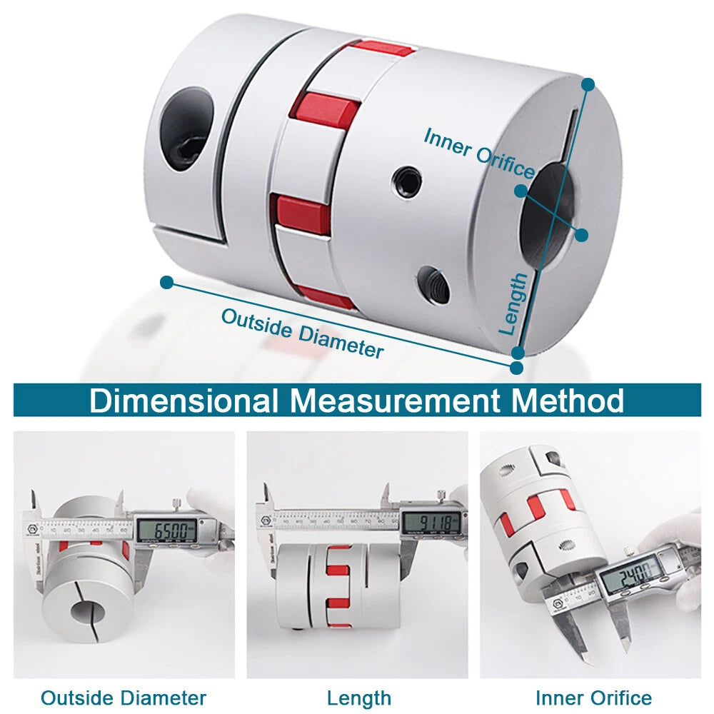
Measure the outer diameter of your motor shaft (d1) and the outer diameter of your lead screw or driven shaft (d2) with a caliper. Select the variant whose d1 × d2 matches those measurements. If both shafts are the same diameter, choose a symmetric bore such as 8 mm × 8 mm. Common NEMA 17 motor shafts are 5 mm or 6.35 mm (¼ in); T8 lead screws are typically 8 mm.

What is the difference between the L66 and L78 body lengths?

Both lengths share the same 40 mm outer diameter and bore options. The L66 (66 mm) version is more compact and suits tight motor-mount enclosures. The L78 (78 mm) version provides extra axial clearance between the motor face and the driven component, which can be useful when the motor shaft protrudes further or when you need more room for the spider insert to flex.

How much misalignment can this coupling handle?

The polyurethane spider insert typically accommodates angular misalignment of approximately 1°–3° and parallel (radial) offset of approximately 0.2–0.5 mm. For best results and longest spider life, align shafts as closely as possible during installation and treat the coupling's misalignment capacity as a tolerance buffer rather than a design target.

Is the spider insert replaceable?

Yes. The two aluminum hubs separate once the set screws are loosened, allowing you to slide out the worn spider element and press in a new one without removing the hubs from the shafts. This makes maintenance straightforward and cost-effective over the life of the machine.

Will this coupler work with my NEMA 17 stepper motor?

Most NEMA 17 motors have a 5 mm shaft. If your motor has a 5 mm shaft, select a variant with d1 = 5 mm. If your motor has a 6.35 mm (¼ in) shaft — common on some higher-torque NEMA 17 and NEMA 23 motors — choose d1 = 6.35 mm. Always verify your motor's shaft diameter in its datasheet before ordering.

How do I install the coupling correctly?

Slide each hub onto its respective shaft until the shaft end is flush with or slightly recessed from the outer face of the hub. Tighten the set screw firmly against the shaft flat (if present) or against the shaft surface. Insert the spider element between the two hubs, then bring the hubs together so the spider lobes seat fully in the hub slots. Verify shaft alignment before final tightening.

What surface finish do the aluminum hubs have?

The hubs are machined from aluminum alloy with a natural or lightly anodized finish. This provides adequate corrosion resistance for indoor workshop and 3D-printer environments. For high-humidity or outdoor applications, consider applying a light coat of machine oil to exposed surfaces.

🛒 Select your Hole (d1 × d2) and Size (D × L) above, then add to cart.

You may also like

Recently viewed