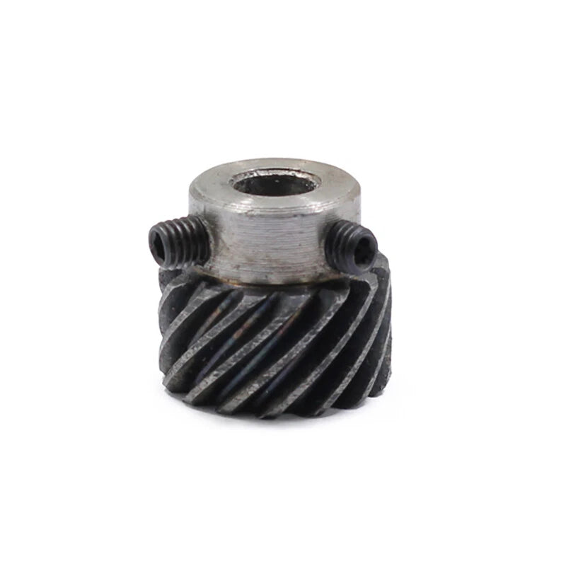
1/1.5/2 Modulus Helical Gear With Step 45° Right Spiral Motor Transmission Gear

No reviews

Price:
Sale price$13.57 USD
Stock:
In stock (500 units), ready to be shipped

Payment & Security

Ach Direct Debit Amazon American Express Apple Pay Bancontact BLIK Diners Club Discover EPS Google Pay iDEAL Wero JCB Maestro Mastercard Multibanco MobilePay PayPal Przelewy24 Shop Pay Twint Union Pay USDC Visa

Your payment information is processed securely. We do not store credit card details nor have access to your credit card information.

Limited Offer — Spend More, Save More
Spend $55+
Save $5
Spend $100+
Save $10
Spend $200+
Save $25
HomeDIYer DIY Expert Support

DIY Expert Support

Get fitment advice & recommendations

Mon–Fri  8:30 AM – 8:00 PM
24-Hour Fast Ship
Arrives in 3–14 Days
Worldwide Shipping
30-Day Returns
1 tree planted with every purchase

Description

Modulus Helical Gear With Step — Precision 45° Right Spiral for Motor Transmission Drives

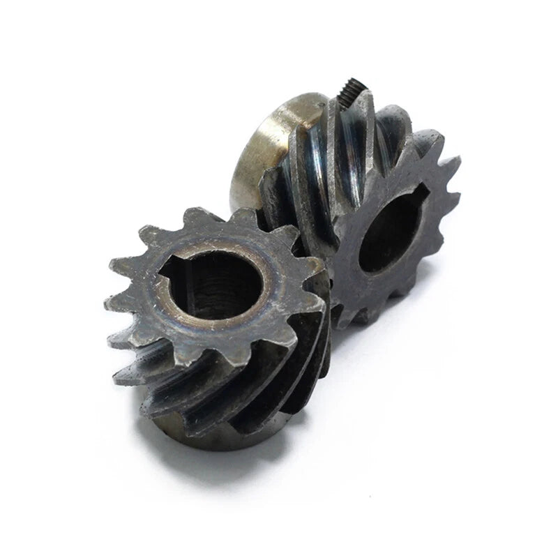
When a standard spur gear introduces too much noise or axial play into your drive train, engineers and makers turn to helical gears for smoother, quieter power transfer. These stepped-bore helical gears are designed for builders working on CNC routers, robotic arms, conveyor drives, and custom motor transmission assemblies who need a reliable, drop-in gear with a defined bore and a consistent helix angle.

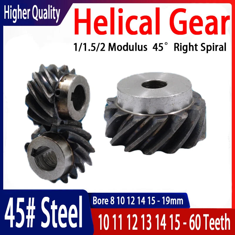
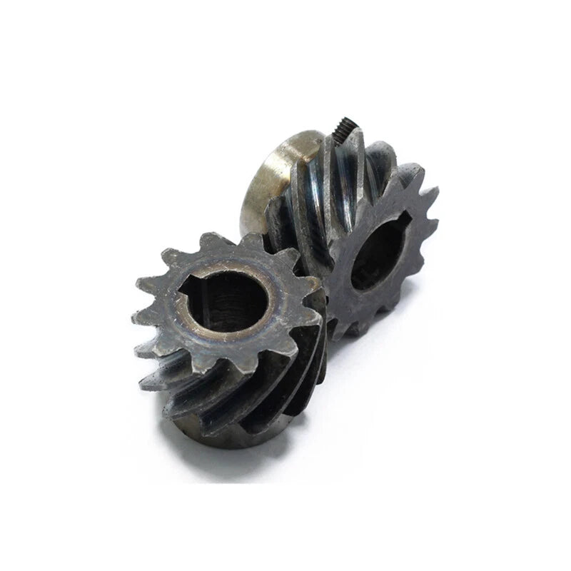
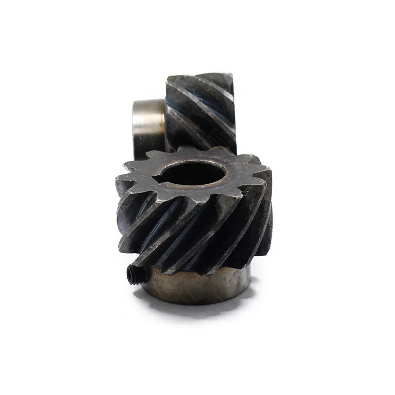
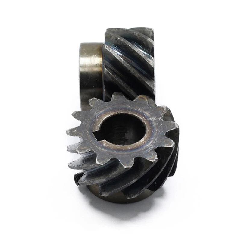
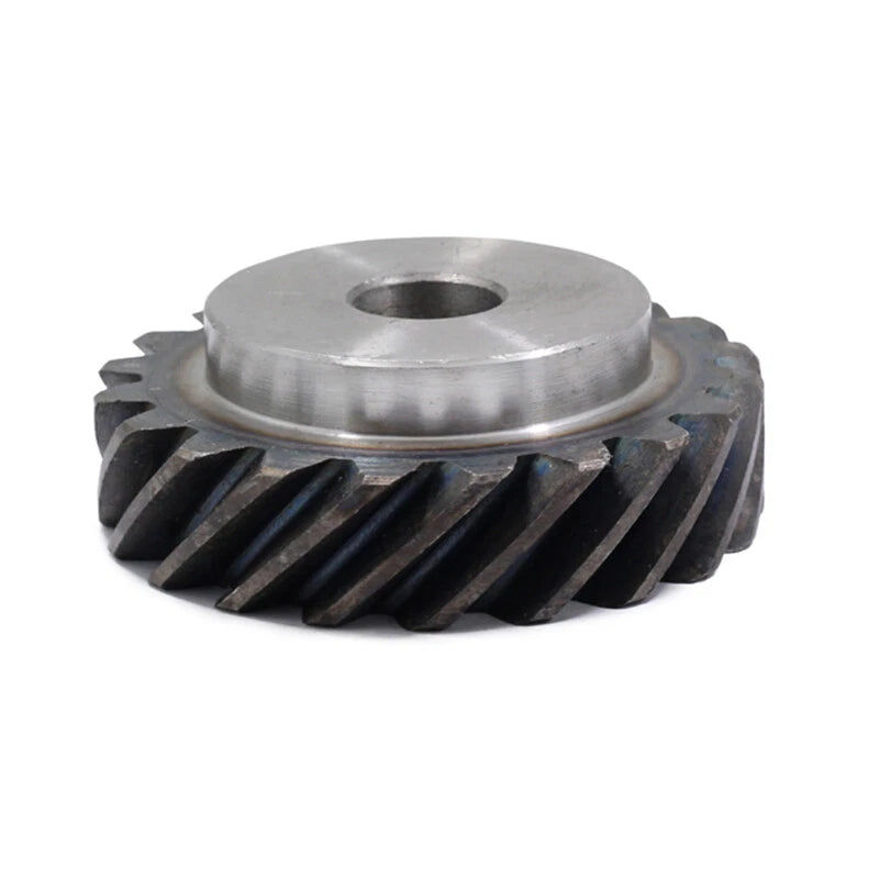
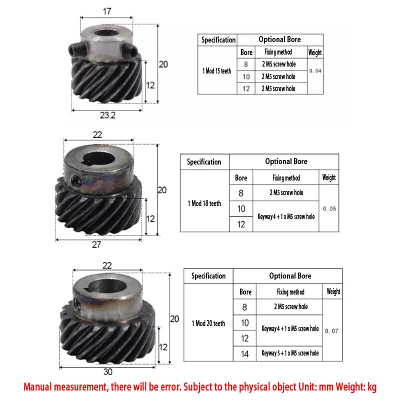
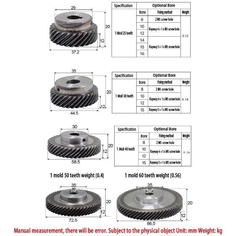
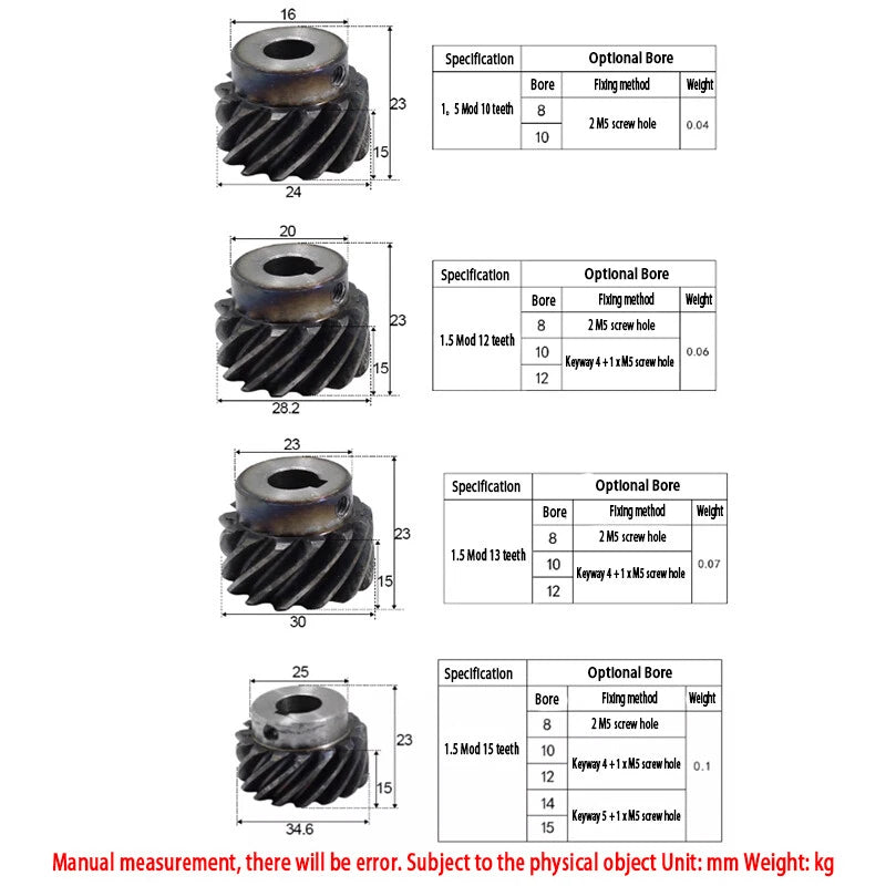
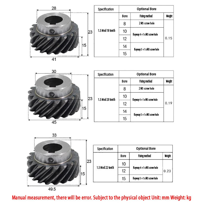
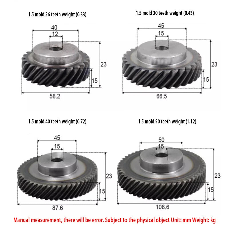
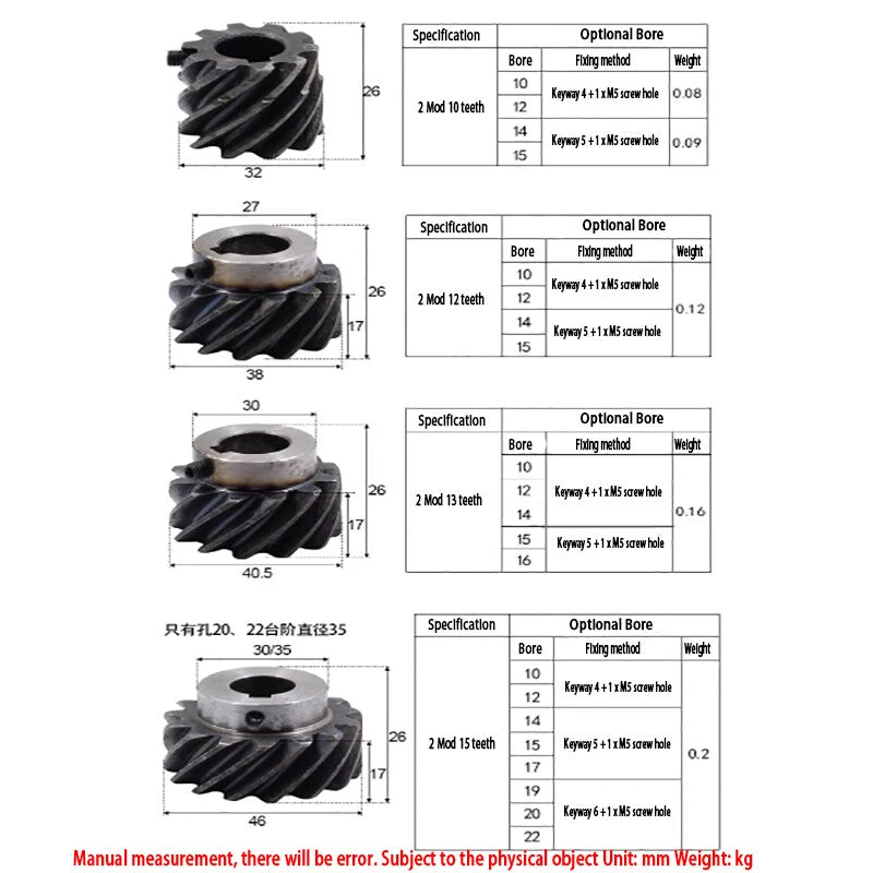
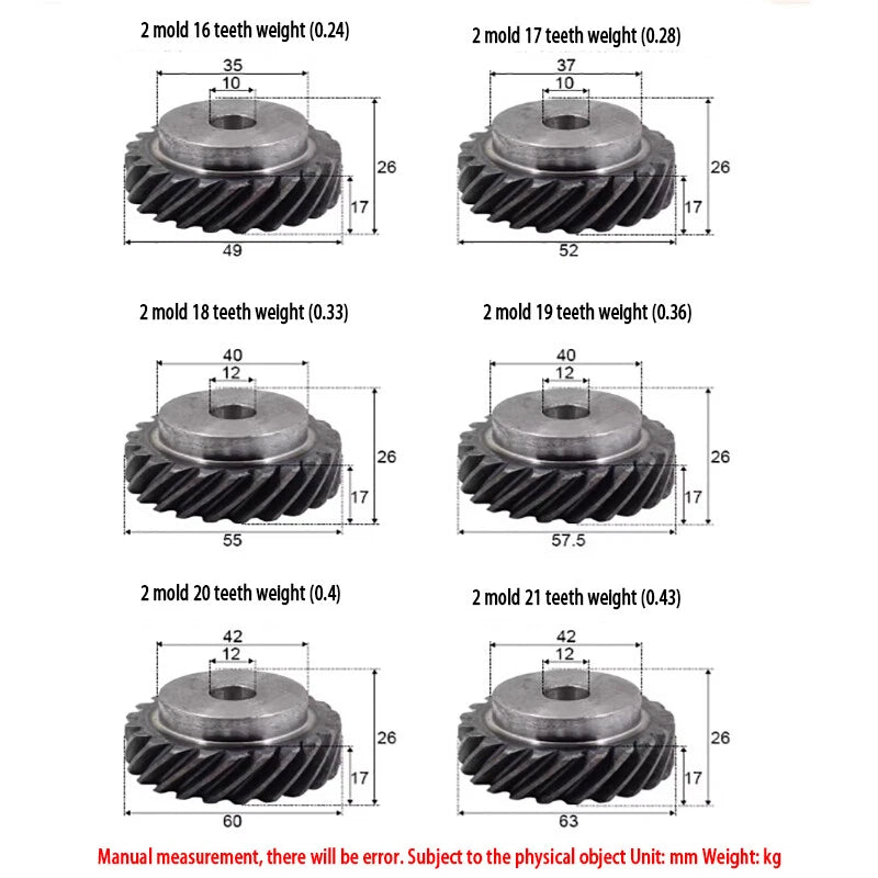
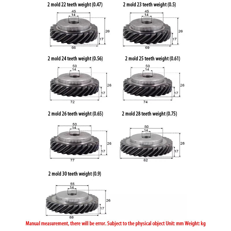
Each gear is machined from 45# carbon steel and features a 45° right-hand spiral angle with an integrated step (shoulder) on the bore side for precise axial positioning. Available in three modulus values — 1, 1.5, and 2 — with tooth counts ranging from 10 to 60 teeth and bore diameters from 8 mm (0.31 in) to 19 mm (0.75 in). Outer diameter scales with modulus and tooth count, typically ranging from approximately 12 mm (0.47 in) for the smallest variants up to 122 mm (4.80 in) for the largest.

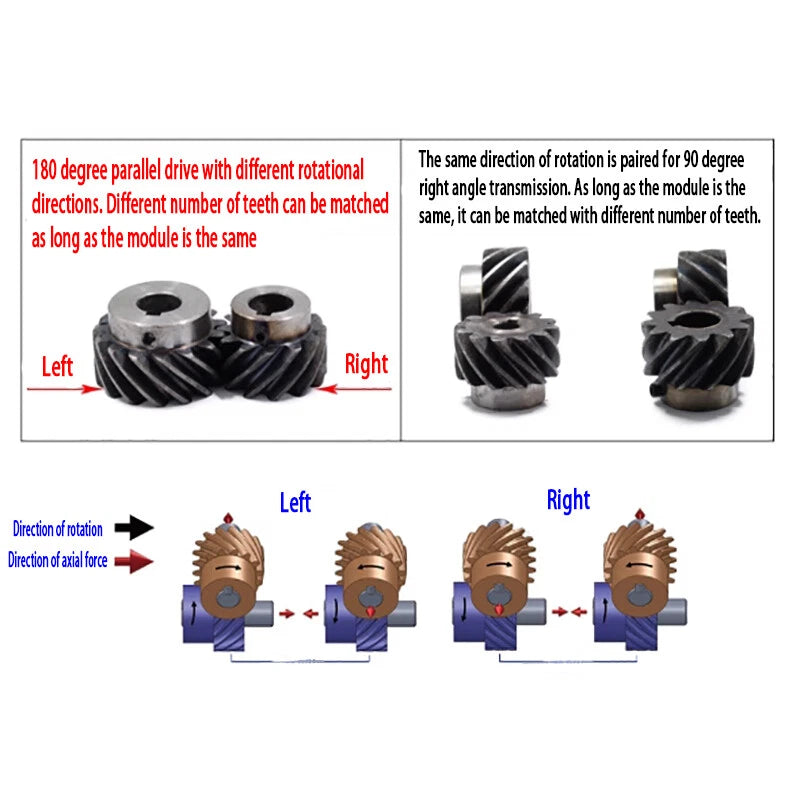
Typical use cases include pairing with a matching left-spiral helical gear for parallel-shaft gearboxes in desktop CNC machines, integrating into stepper or servo motor output shafts for 3D printer extruder drives, and building custom reduction stages for robotic joint actuators where low backlash and quiet operation are critical.

⚙️ Compatibility: Designed to mesh with opposite-hand (left-spiral) helical gears of the same modulus and pressure angle (20°). Verify bore diameter matches your shaft before ordering. Stepped bore provides a shoulder reference face for axial positioning with a retaining ring or set screw.

✅ Key Features of These Modulus Helical Gears

🔩
Three Modulus Options

Available in Modulus 1, 1.5, and 2 to match a wide range of gear ratio and torque requirements across different drive applications.

📐
45° Right-Hand Helix Angle

The 45° spiral angle delivers smooth, progressive tooth engagement that reduces vibration and noise compared to straight-cut spur gears in the same application.

🔧
Stepped Bore for Axial Location

The integrated shoulder step on the bore allows precise axial positioning on the shaft, eliminating the need for additional spacers in most installations.

Wide Teeth & Bore Selection

Choose from 10 to 60 teeth and bore sizes from 8 mm to 19 mm, giving you the flexibility to match your exact shaft diameter and gear ratio target.

🏭
45# Carbon Steel Construction

Machined from 45# medium-carbon steel for a balance of strength, machinability, and wear resistance suitable for continuous-duty motor transmission use.

🎯
20° Pressure Angle Standard

Conforms to the standard 20° pressure angle, ensuring compatibility with off-the-shelf mating helical gears and standard gear-cutting tooling for custom modifications.

📐 Technical Specifications — Helical Transmission Gears

Modulus Options 1 / 1.5 / 2
Helix Angle 45° Right-Hand Spiral
Pressure Angle 20°
Teeth Range 10 – 60 Teeth (see variant options)
Bore Diameter 8 / 10 / 12 / 14 / 15 / 17 / 19 mm (see variant options)
Bore Style Stepped (shouldered) bore
Material 45# Carbon Steel
Outer Diameter See variant options
Face Width See variant options
Quantity per Order 1 PCS
Finish Natural / uncoated machined surface

❓ Frequently Asked Questions

How do I choose the right modulus for my application?

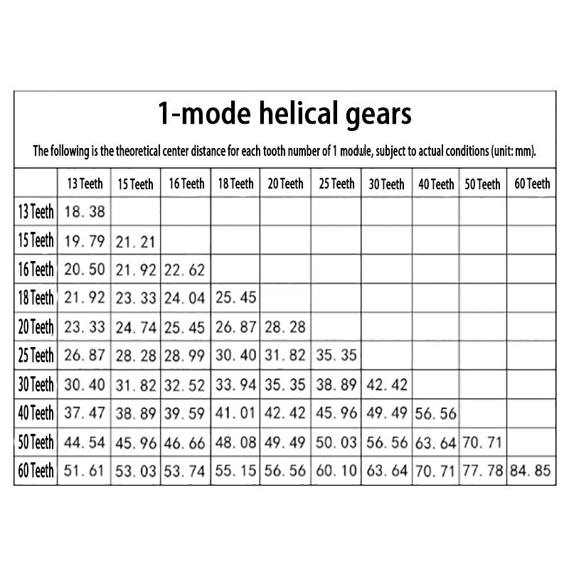
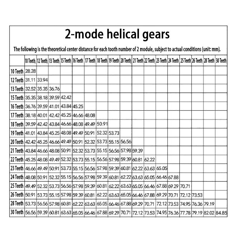
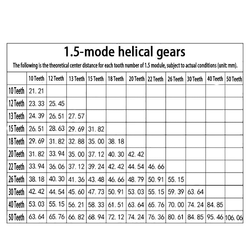
Modulus determines the size of the gear teeth relative to the pitch diameter. A higher modulus (e.g., 2) means larger, stronger teeth suitable for higher torque loads, while a lower modulus (e.g., 1) gives finer teeth for compact, lower-torque drives. Match the modulus to your mating gear and confirm the center distance fits your housing before ordering.

What bore size should I select for my motor shaft?

Measure your motor or gearbox output shaft diameter with a caliper. Select the bore option that matches — available in 8, 10, 12, 14, 15, 17, and 19 mm. The stepped bore provides a shoulder for axial location; you can secure the gear with a set screw or retaining ring in the groove behind the step.

Can this gear mesh with a spur gear of the same modulus?

No. Helical gears must mesh with other helical gears of the same modulus, pressure angle, and opposite hand (a right-hand gear meshes with a left-hand gear on parallel shafts). Mixing helical and spur gears of the same modulus is not recommended as the tooth geometry differs and will cause rapid wear.

Is 45# carbon steel suitable for outdoor or high-humidity environments?

45# carbon steel offers good mechanical strength but has limited corrosion resistance in wet or outdoor environments. For applications exposed to moisture, consider applying a light machine oil coating for protection, or consult us about alternative material options. For dry, enclosed gearbox environments this material performs reliably over extended service life.

How many teeth should I choose to achieve a specific gear ratio?

Gear ratio equals the number of teeth on the driven gear divided by the number of teeth on the driving gear. For example, pairing a 15-tooth driver with a 30-tooth driven gear gives a 2:1 reduction. Select your tooth counts based on your required ratio and verify the resulting center distance fits your mechanical design.

What is the advantage of a 45° helix angle over a lower helix angle?

A 45° helix angle maximizes the overlap ratio, meaning multiple teeth are always in contact simultaneously. This results in very smooth, quiet operation and distributes load across more tooth surface area. The trade-off is a higher axial thrust force on the shaft bearings, so ensure your bearing selection accounts for both radial and axial loads.

Can I use these gears in a 3D printer or CNC router build?

Yes. These gears are well-suited for desktop CNC router spindle drives, extruder gear trains, and Z-axis reduction stages where quiet operation and compact size matter. Select the modulus and tooth count that matches your target gear ratio and confirm the bore fits your stepper or servo motor shaft diameter.

🛒 Select your Modulus, Teeth count, and Gear Bore size above, then add to cart.

You may also like

Recently viewed