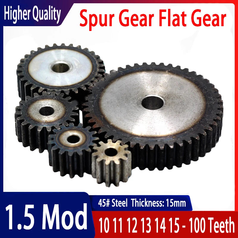
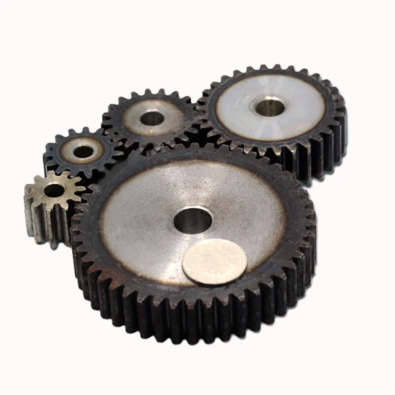
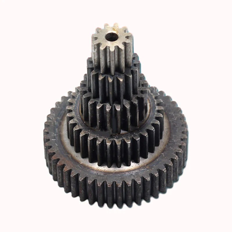
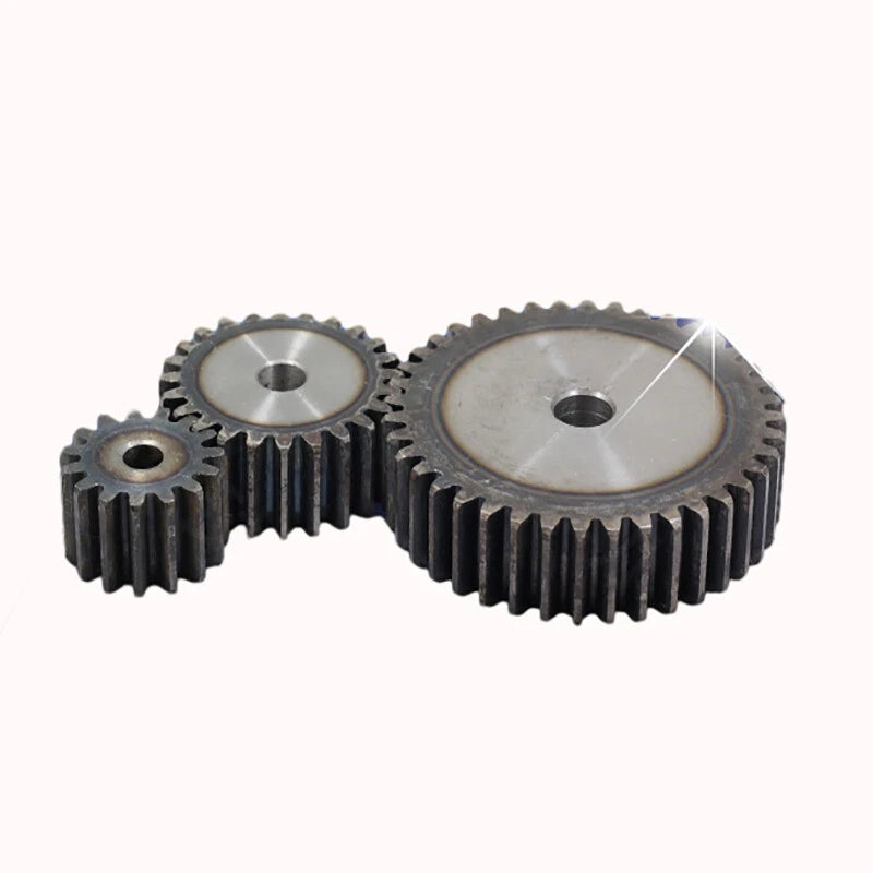
1.5 Mod Spur Gear 10T to 100T Teeth Flat Gear Motor Transmission Gear 45# Steel

No reviews

Price:
Sale price$1.48 USD
Stock:
In stock (500 units), ready to be shipped

Payment & Security

Ach Direct Debit Amazon American Express Apple Pay Bancontact BLIK Diners Club Discover EPS Google Pay iDEAL Wero JCB Maestro Mastercard Multibanco MobilePay PayPal Przelewy24 Shop Pay Twint Union Pay USDC Visa

Your payment information is processed securely. We do not store credit card details nor have access to your credit card information.

Limited Offer — Spend More, Save More
Spend $55+
Save $5
Spend $100+
Save $10
Spend $200+
Save $25
HomeDIYer DIY Expert Support

DIY Expert Support

Get fitment advice & recommendations

Mon–Fri  8:30 AM – 8:00 PM
24-Hour Fast Ship
Arrives in 3–14 Days
Worldwide Shipping
30-Day Returns
1 tree planted with every purchase

Description

1.5 Module Spur Gear — Precision 45# Steel Flat Transmission Gear for Motor Drives

When a motion-control build demands repeatable, low-backlash power transfer, the wrong gear becomes the weakest link in the entire drivetrain. Makers, CNC builders, and automation engineers who need a reliable 1.5 module spur gear in a wide tooth-count range will find this flat transmission gear a dependable drop-in for motor output shafts and reduction stages.

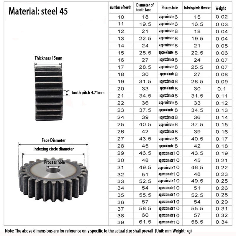
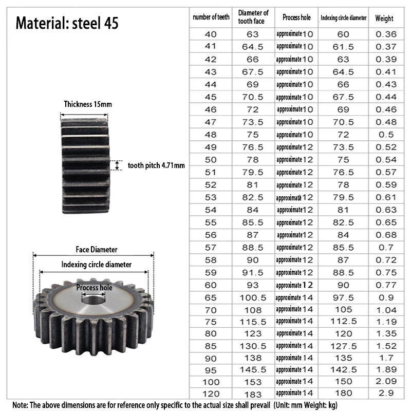
Each gear is machined from 45# medium-carbon steel, offering a balance of machinability and surface hardness suited to moderate-to-heavy load applications. The 1.5 modulus (Module 1.5) standard governs tooth profile geometry, ensuring interchangeability with any mating gear of the same module. Tooth counts span 10 T to 100 T (select your variant), with outer diameters ranging from approximately 18 mm (0.71 in) for the 10-tooth gear up to approximately 153 mm (6.02 in) for the 100-tooth gear, calculated at the standard pitch diameter formula OD ≈ (T + 2) × m.

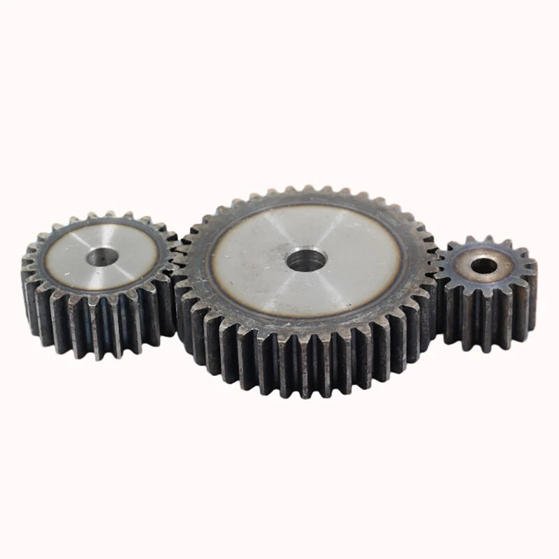
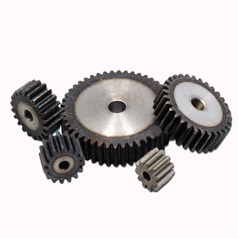
Typical use cases include DIY CNC router Z-axis drives requiring a compact 1.5 mod spur gear for stepper motor coupling, robotics joint reduction stages where a flat gear motor transmission gear keeps the assembly profile low, and small industrial conveyor or indexing mechanisms that need a standardized 45-steel gear for long service intervals.

⚙️ Compatibility: Fits any mating spur gear of Module 1.5 (Mod 1.5 / m1.5). Bore diameter varies by tooth count — confirm bore size from variant listing before ordering. Suitable for parallel-shaft gear trains; not intended for helical or bevel gear applications.

✅ Key Features of These 1.5 Module Spur Gears

🔩
45# Steel Construction

Medium-carbon 45# steel delivers solid tensile strength and wear resistance for motor transmission and reduction gear applications under sustained load.

📐
Module 1.5 Standard Profile

Tooth geometry conforms to the Module 1.5 international standard, ensuring direct mesh compatibility with any m1.5 rack, pinion, or mating spur gear.

🎯
Wide Tooth-Count Range (10 T – 100 T)

Select from 10 to 100 teeth in a single product listing to dial in your exact gear ratio without sourcing from multiple suppliers.

Flat Gear Profile for Compact Assemblies

The flat (straight-cut) spur design keeps axial forces near zero, making it ideal for thin-profile motor mounts and space-constrained CNC or robotics frames.

🔄
Consistent Pitch Accuracy

Machined tooth spacing maintains consistent pitch circle diameter across the full tooth-count range, supporting smooth, low-vibration power transfer in indexing and drive applications.

🛠️
Machinable for Custom Bore Sizing

45# steel responds well to lathe boring and keyway milling, allowing the bore to be opened or keyed to match non-standard motor shaft diameters on the workbench.

📐 Technical Specifications — 1.5 Module Spur Gear

Gear Module (m) 1.5
Tooth Count Range 10 T – 100 T (see variant options)
Material 45# Medium-Carbon Steel
Gear Type Spur Gear (straight-cut, flat face)
Pressure Angle 20° (standard)
Pitch Diameter m × T (e.g., 1.5 × 20 = 30 mm for 20T)
Outer Diameter (approx.) (T + 2) × 1.5 mm — see variant options
Bore Diameter See variant options
Face Width (Hub Thickness) See variant options
Surface Finish See variant options
Weight See variant options
Package Contents 1 PCS spur gear (per unit ordered)

❓ Frequently Asked Questions

How do I choose the right tooth count for my gear ratio?

Divide the driven gear tooth count by the driver gear tooth count to get your reduction ratio. For example, pairing a 20-tooth driver with a 60-tooth driven gear gives a 3:1 reduction. Select the tooth count that achieves your target ratio when meshed with your existing pinion or rack. All gears in this listing share Module 1.5, so any two variants will mesh correctly with each other.

Will this gear mesh with my existing Module 1.5 rack or pinion?

Yes. Any gear marked Module 1.5 (m1.5) with a 20° pressure angle will mesh with any other m1.5 component regardless of tooth count. Confirm that your existing rack or pinion is also Module 1.5 before ordering — mixing modules (e.g., m1.0 with m1.5) will result in incorrect mesh and accelerated wear.

How strong is 45# steel for motor transmission applications?

45# medium-carbon steel has a typical tensile strength of approximately 600–800 MPa in the normalized condition, making it suitable for moderate-torque motor drives, CNC axis feeds, and light industrial indexing. For very high-torque or shock-load applications, consider heat-treated variants or upgrading to alloy steel gears. For most hobby CNC, robotics, and small automation builds, 45# steel provides adequate service life.

Is this gear corrosion-resistant for outdoor or humid environments?

45# carbon steel is not inherently corrosion-resistant. For outdoor, humid, or washdown environments, apply a light machine oil or grease coating during operation, or consider a zinc-plated or stainless-steel alternative. For indoor CNC and robotics enclosures with controlled humidity, bare 45# steel performs well with standard lubrication maintenance.

Can I modify the bore diameter to fit my motor shaft?

Yes. 45# steel is readily machinable on a lathe. The bore can be opened to a larger diameter or a keyway can be milled to accept a keyed shaft. Ensure the remaining wall thickness after boring is sufficient for your torque load — as a conservative guideline, maintain at least 3–5 mm of wall between the bore and the root circle of the teeth.

What is the difference between a flat spur gear and a helical gear, and which should I choose?

Spur gears (like this one) have straight teeth parallel to the gear axis, producing no axial thrust force and making them easy to install and replace. They are the correct choice for most CNC, robotics, and general automation drives where simplicity and interchangeability matter. Helical gears have angled teeth that engage more gradually, producing lower noise at high speeds but generating axial thrust that requires thrust bearings. Choose this spur gear for straightforward parallel-shaft drives; choose helical gears only if noise at high RPM is a primary concern and your design accommodates thrust loads.

How do I calculate the center distance between two meshing gears?

Center distance = (T1 + T2) × m ÷ 2, where T1 and T2 are the tooth counts of the two meshing gears and m is the module (1.5). For example, a 20-tooth and a 40-tooth gear: (20 + 40) × 1.5 ÷ 2 = 45 mm center distance. Use this formula to set your shaft spacing accurately during frame design.

🛒 Select your gear tooth count (and quantity) above, then add to cart.

You may also like

Recently viewed