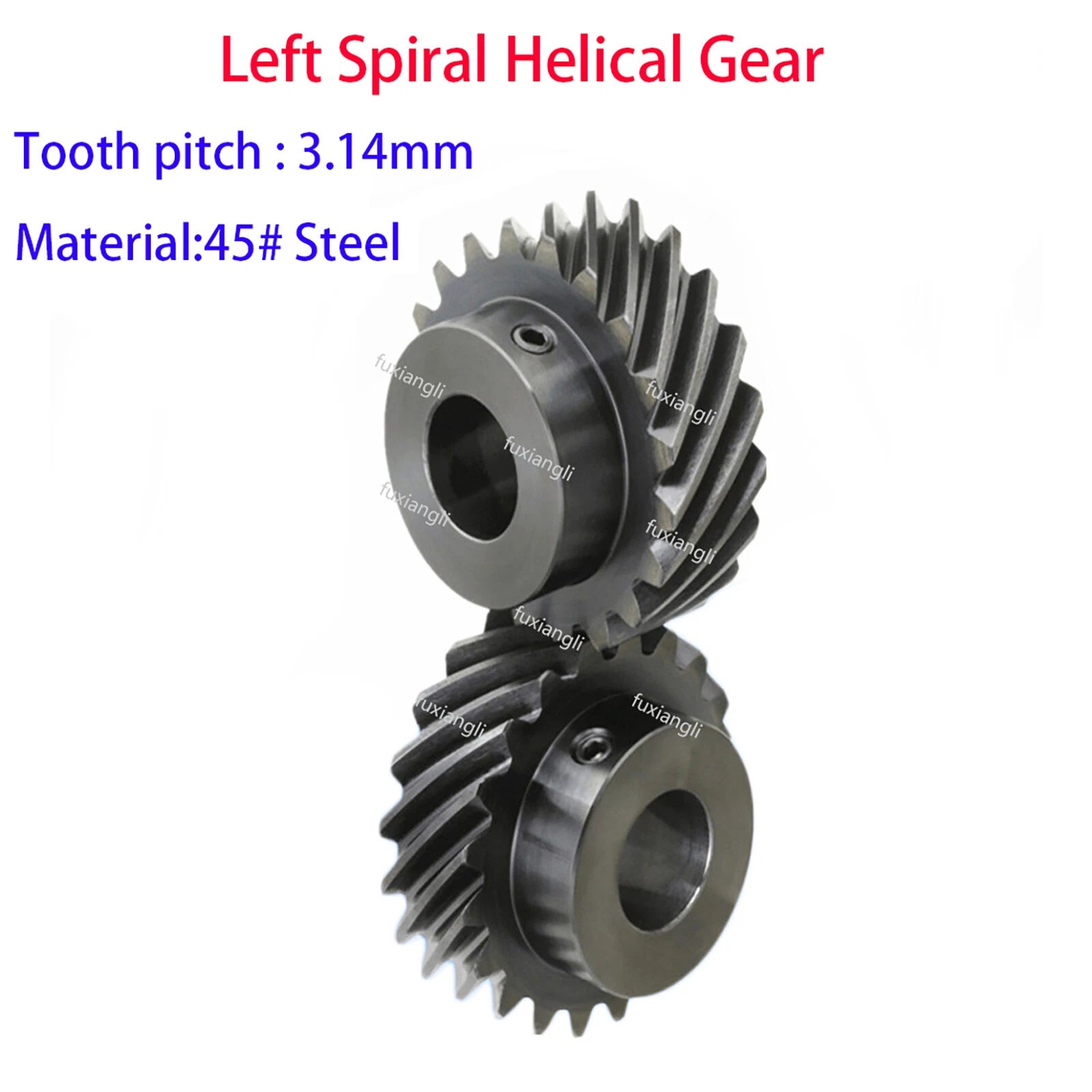
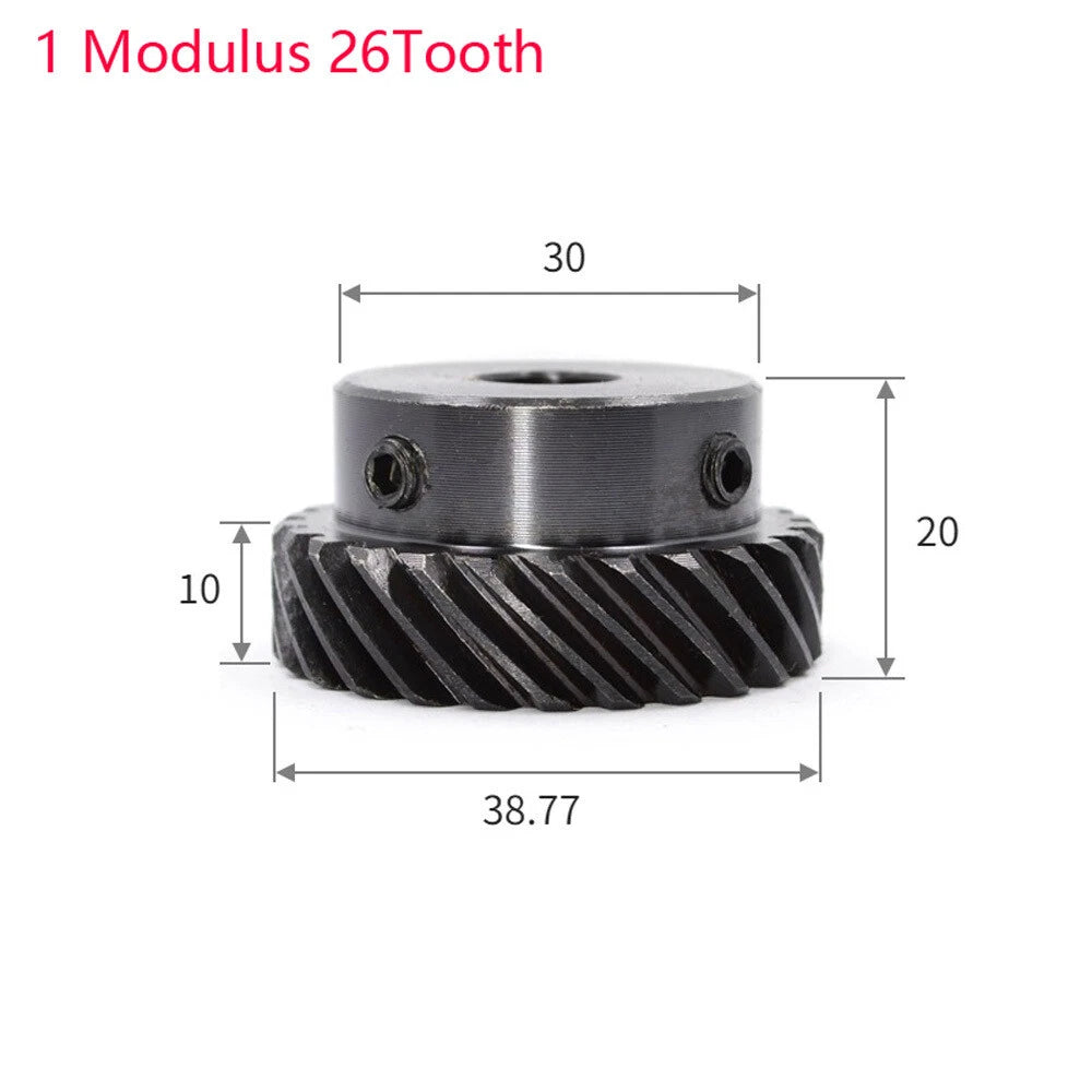
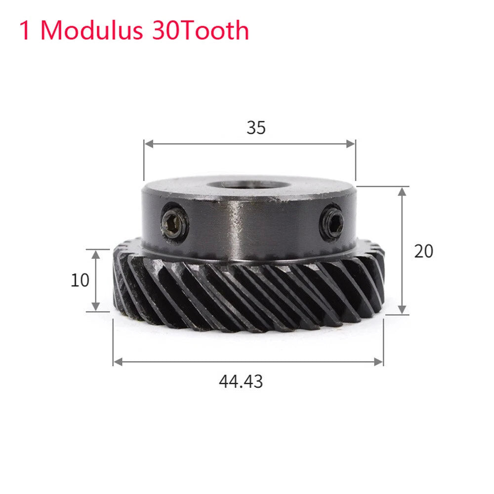
1 Modulus Helical Gear With Step 45°Left Spiral Motor Transmission Gear 45#Steel

No reviews

Price:
Sale price$4.47 USD
Stock:
In stock (500 units), ready to be shipped

Payment & Security

Ach Direct Debit Amazon American Express Apple Pay Bancontact BLIK Diners Club Discover EPS Google Pay iDEAL Wero JCB Maestro Mastercard Multibanco MobilePay PayPal Przelewy24 Shop Pay Twint Union Pay USDC Visa

Your payment information is processed securely. We do not store credit card details nor have access to your credit card information.

Limited Offer — Spend More, Save More
Spend $55+
Save $5
Spend $100+
Save $10
Spend $200+
Save $25
HomeDIYer DIY Expert Support

DIY Expert Support

Get fitment advice & recommendations

Mon–Fri  8:30 AM – 8:00 PM
24-Hour Fast Ship
Arrives in 3–14 Days
Worldwide Shipping
30-Day Returns
1 tree planted with every purchase

Description

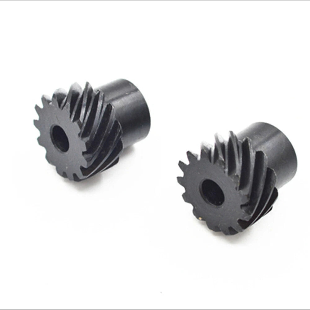
1 Modulus Helical Gear with Step — 45° Left Spiral Transmission Gear for Precision Motion Control

When your CNC router, robotic arm, or motor-driven mechanism demands smooth, low-noise power transfer, a poorly matched gear becomes the weakest link in the entire drivetrain. Engineers, makers, and automation builders who need reliable helical gear engagement without backlash-induced vibration will find this 1 modulus left-spiral stepped gear a dependable solution for demanding applications.

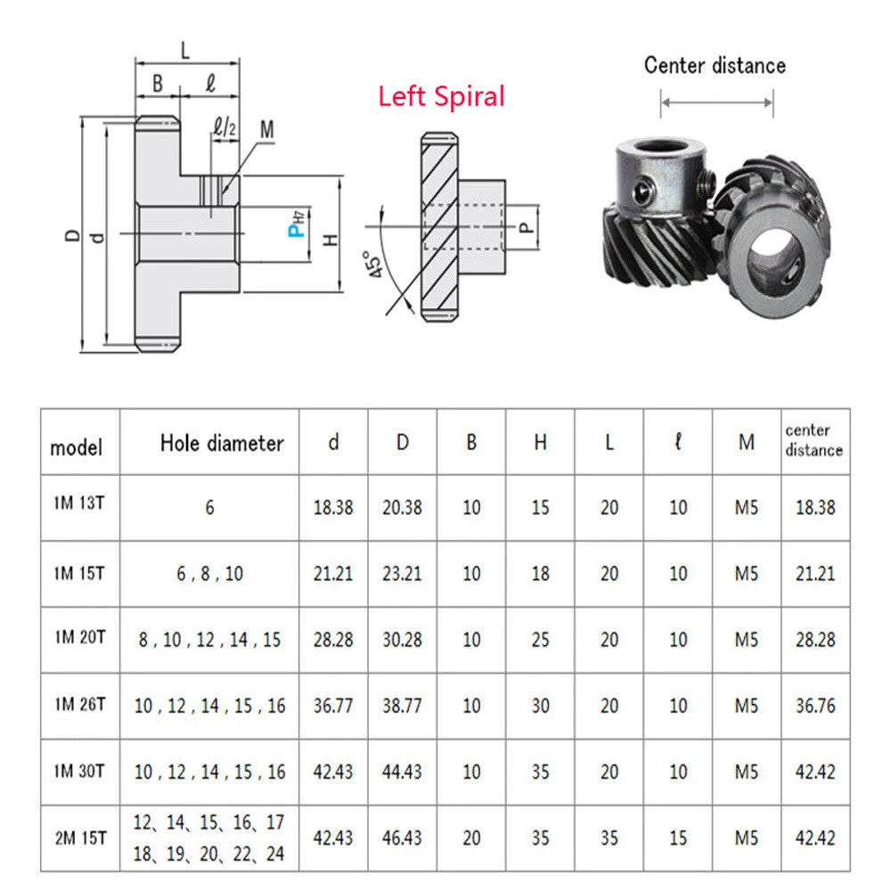
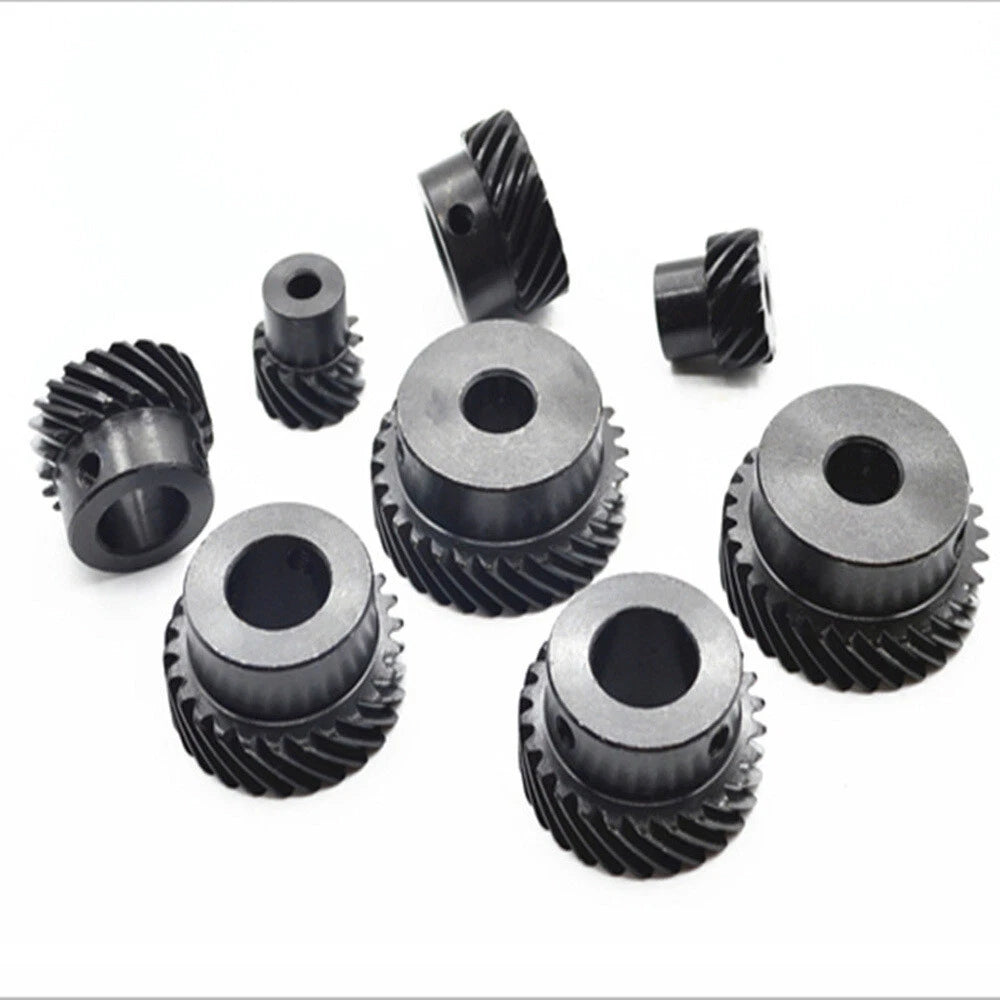
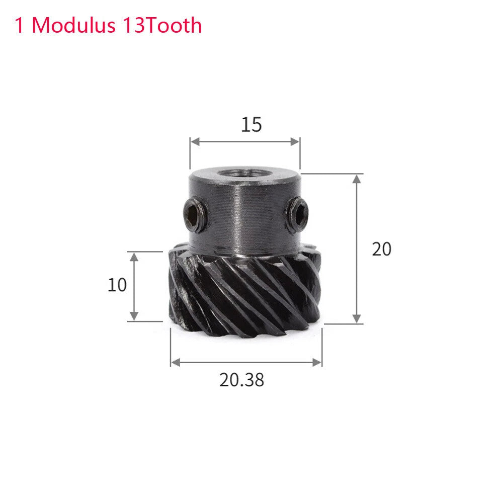
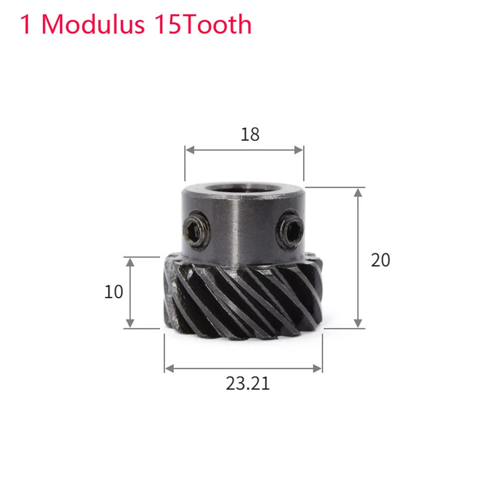
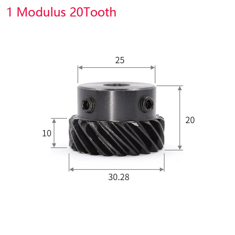
Each gear is machined from 45# carbon steel, offering a solid balance of tensile strength and machinability. The stepped hub design allows secure shaft mounting across bore diameters ranging from 6 mm (0.24 in) to 16 mm (0.63 in). Tooth counts span 13T, 15T, 20T, 26T, and 30T — covering a wide range of gear ratios for speed reduction or torque multiplication. The 45° left-hand helix angle ensures gradual tooth engagement, reducing impact load and operating noise compared to straight-cut spur gears.

Typical use cases include DC motor output shafts in tabletop CNC machines, stepper-driven axis drives in 3D printer extruder assemblies, and paired helical gear sets in custom gearbox builds for robotics competitions or industrial automation prototypes. The consistent 1-modulus pitch makes cross-pairing with standard metric gear racks and mating gears straightforward.

⚙️ Compatibility: Designed for 1 modulus metric gear systems. Pairs with standard 1M gear racks, pinions, and mating helical gears. Bore options: 6 / 8 / 10 / 12 / 14 / 15 / 16 mm. Verify shaft diameter and helix hand (left spiral) before ordering.

✅ Key Features of These 1 Modulus Helical Gears

🔩
45# Carbon Steel Construction

Machined from 45# medium-carbon steel for reliable strength under continuous rotational load, suitable for motor transmission and automation drivetrain applications.

🌀
45° Left-Hand Helix Angle

The left-spiral 45° helix promotes gradual tooth engagement, distributing load across multiple teeth simultaneously to reduce noise and vibration in high-speed drives.

📐
Stepped Hub for Secure Shaft Fit

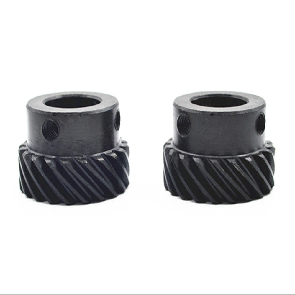
The integrated step on the hub provides a positive axial stop for shaft positioning, simplifying assembly and improving concentricity in tight-tolerance builds.

🎯
Wide Tooth Count Selection (13T–30T)

Five tooth count options — 13, 15, 20, 26, and 30 teeth — let you dial in the gear ratio needed for your specific speed-torque requirement without custom machining.

🔧
Broad Bore Diameter Range (6–16 mm)

Seven bore sizes from 6 mm to 16 mm accommodate a wide variety of motor and gearbox output shafts, reducing the need for adapter sleeves or custom boring.

📏
Standard 1 Modulus Metric Pitch

The 1M pitch is fully compatible with standard metric gear racks and mating gears, making integration into existing 1-modulus drivetrain systems straightforward and repeatable.

📐 Technical Specifications — 1 Modulus Helical Gear

Module 1
Helix Angle 45°
Helix Direction Left (Left Spiral)
Tooth Count Options 13T / 15T / 20T / 26T / 30T
Bore Diameter Options 6 mm / 8 mm / 10 mm / 12 mm / 14 mm / 15 mm / 16 mm
Material 45# Carbon Steel
Hub Style Stepped Hub
Pitch System Metric (1 Modulus)
Surface Finish See variant options
Overall Diameter See variant options
Face Width See variant options
Keyway See variant options
Set Screw See variant options
Weight See variant options

❓ Frequently Asked Questions

How do I choose the right tooth count for my application?

Select the tooth count based on your required gear ratio. Pair a lower tooth count (e.g., 13T or 15T) on the driving shaft with a higher tooth count on the driven shaft for speed reduction and torque increase. For a 1:1 ratio, use matching tooth counts on both gears. Refer to your drivetrain's speed and torque requirements to determine the ideal pairing.

What bore diameter should I order?

Measure your motor or gearbox output shaft diameter precisely with calipers. Select the bore size that matches your shaft — available in 6, 8, 10, 12, 14, 15, and 16 mm. If your shaft has a keyway, confirm whether the bore includes a matching keyway slot before ordering.

Is this gear compatible with standard metric gear racks?

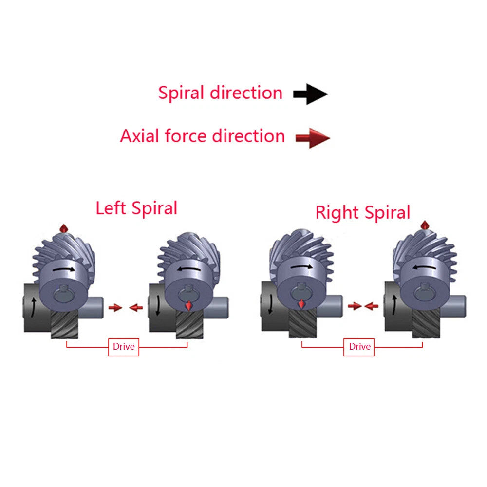
Yes. This gear uses a standard 1 modulus (1M) metric pitch, which is compatible with any 1M metric gear rack or mating helical gear of the same module. Ensure the mating gear also uses a left-hand helix if you need parallel-axis engagement, or a right-hand helix for crossed-axis configurations.

How strong is 45# carbon steel for motor transmission use?

45# carbon steel (equivalent to AISI 1045) has a tensile strength typically in the range of 600–800 MPa in normalized condition, making it well-suited for moderate-to-high load motor transmission applications. It offers a good balance of machinability and mechanical strength for CNC, robotics, and automation drivetrain use.

Does the left-spiral helix direction matter for my build?

Yes — helix direction matters for parallel-axis gear pairs. Two mating gears on parallel shafts must have opposite helix hands (one left, one right) to mesh correctly. If you are replacing an existing gear, confirm the helix direction of the mating gear before ordering. For crossed-axis or worm-style configurations, consult your drivetrain design specifications.

What is the stepped hub design and why does it help?

The stepped hub features a shoulder (step) machined into the hub body that acts as a positive axial stop when the gear is pressed or slid onto a shaft. This simplifies assembly by providing a consistent reference position, improving concentricity and reducing the chance of misalignment during installation — particularly useful in precision CNC and robotics builds.

Can I use this gear in a high-speed application?

The 45° helical tooth form is well-suited for higher-speed applications compared to straight-cut spur gears, as the gradual tooth engagement reduces impact load and noise. Actual maximum speed depends on your lubrication, shaft support (bearing arrangement), and load conditions. For sustained high-speed use, ensure adequate lubrication and proper shaft alignment.

🛒 Select your tooth count and bore diameter above, then add to cart.

You may also like

Recently viewed