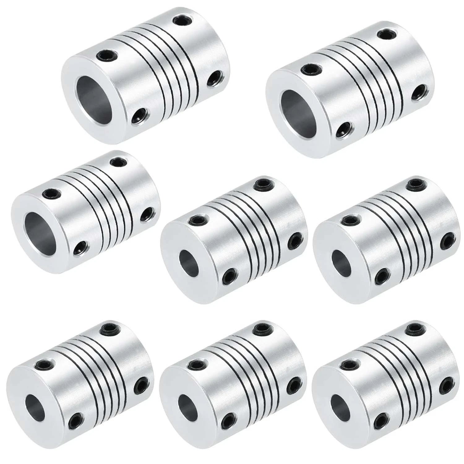
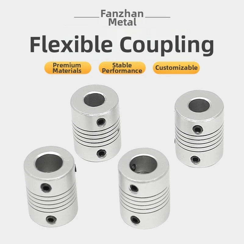
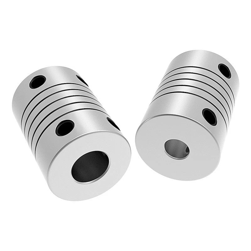
Flexible Shaft Coupling Connector Coupler CNC 3D Printer Stepper Motor 8 - 24mm

No reviews

Price:
Sale price$40.77 USD
Stock:
In stock (500 units), ready to be shipped

Payment & Security

Ach Direct Debit Amazon American Express Apple Pay Bancontact BLIK Diners Club Discover EPS Google Pay iDEAL Wero JCB Maestro Mastercard Multibanco MobilePay PayPal Przelewy24 Shop Pay Twint Union Pay USDC Visa

Your payment information is processed securely. We do not store credit card details nor have access to your credit card information.

Limited Offer — Spend More, Save More
Spend $55+
Save $5
Spend $100+
Save $10
Spend $200+
Save $25
HomeDIYer DIY Expert Support

DIY Expert Support

Get fitment advice & recommendations

Mon–Fri  8:30 AM – 8:00 PM
24-Hour Fast Ship
Arrives in 3–14 Days
Worldwide Shipping
30-Day Returns
1 tree planted with every purchase

Description

Flexible Shaft Coupling for CNC & 3D Printer Stepper Motors — Precise, Vibration-Damping Connection

Misaligned motor shafts and rigid couplings are a leading cause of lost steps, premature bearing wear, and print-quality failures in CNC routers and 3D printers. Engineers, makers, and machine builders who need a reliable, forgiving connection between a stepper motor and a lead screw or ball screw rely on a flexible shaft coupling to absorb angular and parallel misalignment without transmitting shock loads back into the motor bearings.

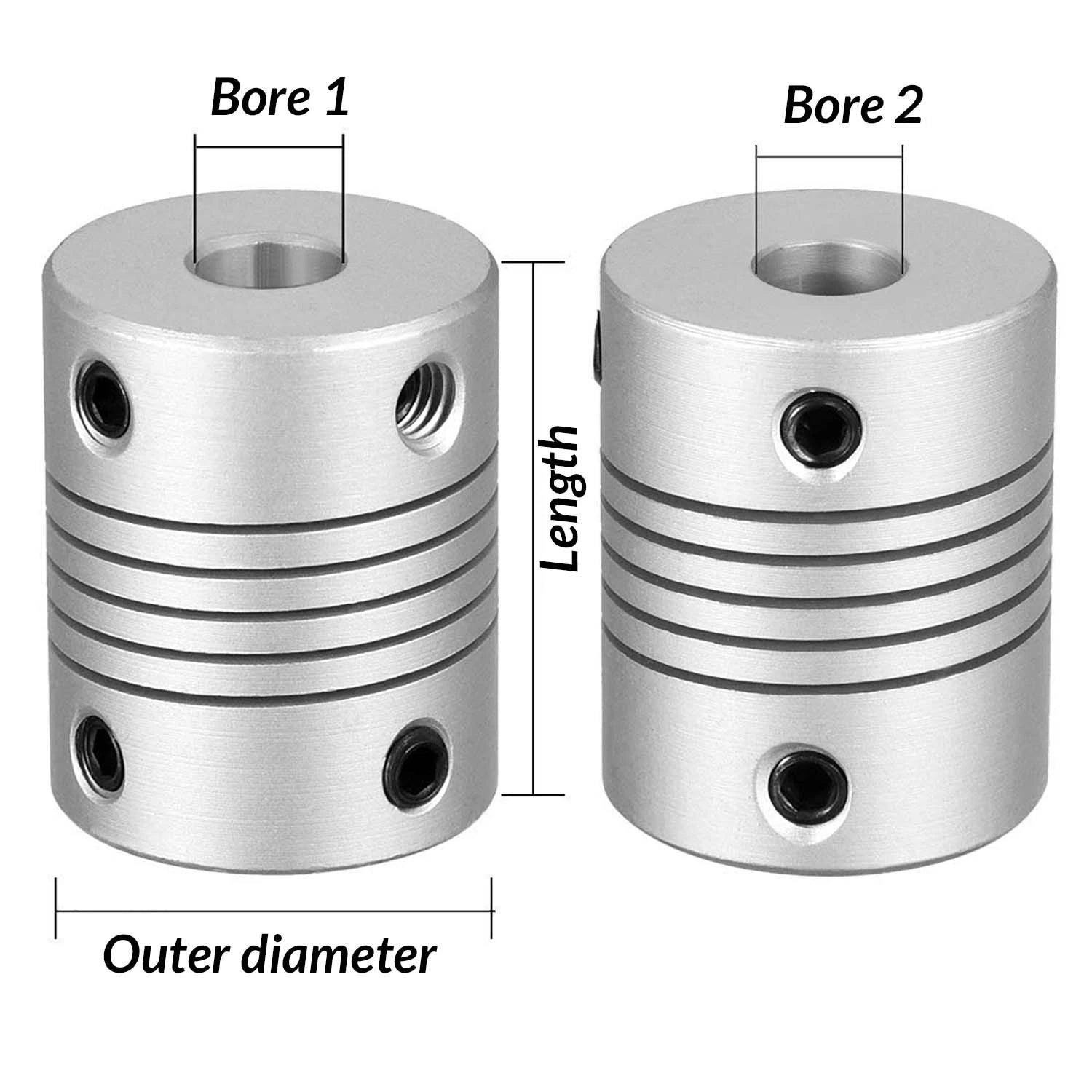
This flexible shaft coupling is a jaw-type (spider) coupler machined from aluminum alloy hubs with a polyurethane spider insert. Available outer diameters range from Ø38 mm (≈1.50 in) to Ø50 mm (≈1.97 in), with body lengths from 41 mm (≈1.61 in) to 71 mm (≈2.80 in). Bore combinations span 8 mm through 24 mm on both the drive and driven sides, covering the most common stepper motor shaft and lead-screw shaft diameters used in desktop and industrial motion systems.

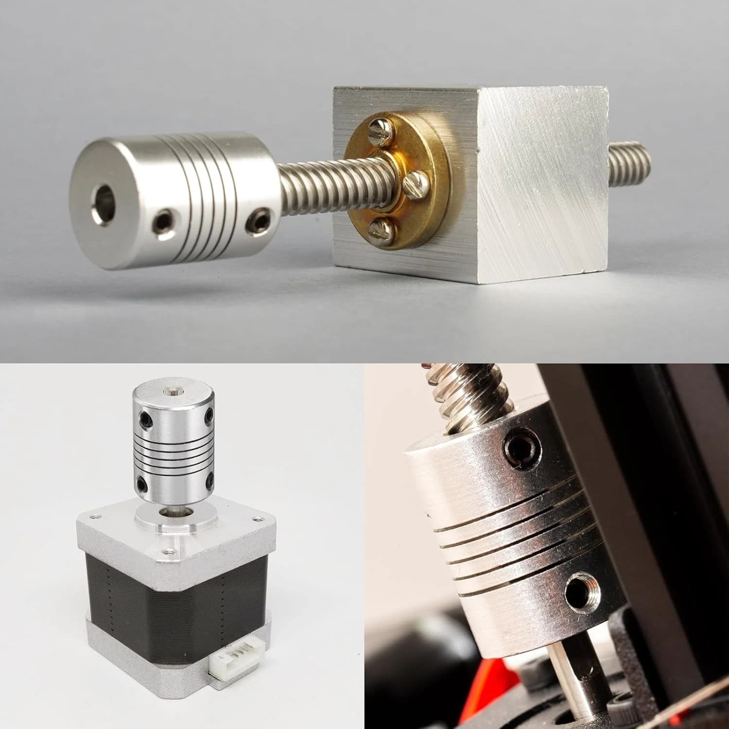
Typical use cases include connecting NEMA 17 or NEMA 23 stepper motors to T8 or T12 lead screws in 3D printer Z-axis assemblies, coupling servo motors to ball screws in CNC router gantries, and linking encoder shafts to drive shafts in automated conveyor systems where vibration isolation is critical.

⚙️ Compatible with: NEMA 17 / NEMA 23 stepper motors · T8 / T12 lead screws · 5 mm – 24 mm ball screw shafts · CNC routers · 3D printer Z-axis · Servo motor drives · Encoder couplings

✅ Key Features of These Flexible Shaft Couplings

  • 🔩 Jaw-Type Spider Design — The polyurethane spider insert sits between two aluminum hubs, absorbing angular misalignment (typically up to 1°) and parallel offset while transmitting torque smoothly, reducing vibration transmitted to motor bearings.
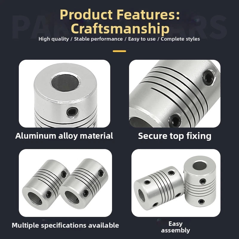
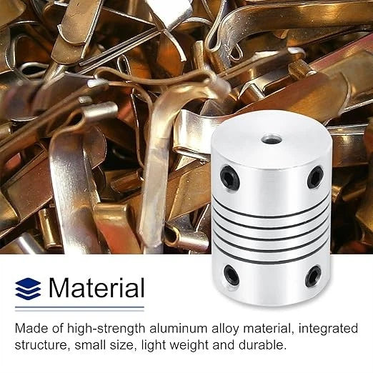
  • 🏗️ Aluminum Alloy Hubs — Machined aluminum construction keeps rotating mass low for fast acceleration and deceleration cycles, important in high-speed CNC and 3D printing applications.
  • 📐 Wide Bore Range: 8 mm – 24 mm — Dual-bore configuration (drive side / driven side) covers the most common stepper motor shaft and lead-screw combinations without adapters or sleeves.
  • 📏 Multiple OD × Length Options — Four body sizes (Ø38×41 mm, Ø40×56 mm, Ø50×50 mm, Ø50×71 mm) let you match the coupling to your available shaft engagement length and torque requirement.
  • 🔧 Set-Screw Clamping — Each hub is secured to its shaft via set screws, allowing tool-free bore adjustment and quick shaft swaps during machine reconfiguration or maintenance.
  • 🛡️ Vibration & Shock Damping — The elastomeric spider insert dampens torsional shock and reduces resonance, protecting stepper motor encoders and lead-screw nuts from impact loads during direction reversals.

📐 Technical Specifications — Flexible Jaw Shaft Coupling

Coupling Type Jaw / Spider (Oldham-style elastomeric insert)
Hub Material Aluminum alloy
Spider Insert Material Polyurethane (PU)
Outer Diameter × Body Length Ø38 mm × 41 mm / Ø40 mm × 56 mm / Ø50 mm × 50 mm / Ø50 mm × 71 mm
Bore Range (Drive / Driven) 8 mm – 24 mm (see variant options for specific combinations)
Bore Combination See variant options
Finish Natural anodized / mill finish aluminum
Fastening Method Set screw
Angular Misalignment Tolerance Typically up to 1°
Parallel Misalignment Tolerance See variant options
Weight See variant options
Quantity per Order 1 piece

❓ Frequently Asked Questions

How do I choose the right bore size for my stepper motor and lead screw?

Measure the shaft diameter of your stepper motor output shaft (commonly 5 mm for NEMA 17, 6.35 mm / ¼ in for some NEMA 23, or 8 mm for larger NEMA 23 motors) and the diameter of your lead screw or ball screw input end. Select the bore combination that matches both shafts — for example, if your motor shaft is 8 mm and your lead screw is 10 mm, choose the 8 mm/10 mm bore variant. The "Bore (Dia/Dia)" option on this listing shows the drive-side bore first and the driven-side bore second.

What outer diameter and length should I select?

Choose the smallest OD that accommodates your bore combination while fitting within your machine's clearance envelope. The Ø38 mm × 41 mm body suits compact desktop 3D printers with limited Z-axis clearance. The Ø50 mm × 71 mm body provides more shaft engagement length and higher torque capacity, making it suitable for larger CNC routers or servo-driven axes. If torque is the primary concern, a longer body generally provides a more secure set-screw grip.

Can this coupling handle misalignment between my motor and lead screw?

Yes. The jaw-type design with a polyurethane spider insert accommodates angular misalignment of typically up to 1° and small amounts of parallel (radial) offset. However, for best results and longest coupling life, align your motor and lead screw as closely as possible during installation. Excessive misalignment accelerates spider wear and can introduce vibration rather than damping it.

Is this coupling suitable for high-speed CNC spindle connections?

This jaw coupling is designed for low-to-medium speed torque transmission applications such as stepper and servo motor drives, lead screws, and encoder connections — not for high-RPM spindle-to-collet connections. For spindle applications requiring speeds above approximately 3,000 RPM, a balanced rigid or disc coupling is typically more appropriate. Contact us to confirm suitability for your specific RPM and torque requirements.

How do I install and secure the coupling to the shafts?

Slide each hub onto its respective shaft, insert the polyurethane spider between the two hubs, and tighten the set screws with an appropriate hex key (Allen wrench). Ensure the set screws bear against a flat on the shaft where possible to prevent shaft rotation. Do not overtighten — snug the set screws firmly but avoid stripping the threads. Re-check tightness after the first few hours of operation as the spider may compress slightly during initial break-in.

Will the aluminum hubs corrode in a workshop environment?

Aluminum alloy has inherent corrosion resistance due to its natural oxide layer, making it suitable for typical indoor workshop and machine enclosure environments. It is not recommended for continuous exposure to saltwater, strong acids, or alkaline cutting fluids. If your application involves coolant exposure, wipe the coupling dry after use and inspect the spider insert periodically for chemical degradation.

How often should I replace the polyurethane spider insert?

Spider insert lifespan depends on operating torque, misalignment, temperature, and duty cycle. In typical 3D printer or light CNC use, the spider can last for years without replacement. Signs of wear include increased backlash, visible cracking or chunking of the spider, or unusual vibration during operation. Inspect the spider every 6–12 months in continuous-duty applications. The aluminum hubs are reusable — only the spider insert needs replacement when worn.

🛒 Select your Outer dia × Length and Bore (Dia/Dia) above, then add to cart.

You may also like

Recently viewed